As someone who works, and occasionally lives, out of the back of my ute I want to make the most efficient use of space possible – as a result I was naturally drawn towards the idea of getting a set of cargo drawers. But there were three problems:
- I wanted my ute drawers to be modular, so that I could easily remove all, or half, of them to retain flexibility with how I used my ute tray. Most off the shelf and custom drawers were very permanent arrangements.
- Any off the shelf pre-built drawer systems just didn’t realise the space efficiency that I needed. None were the exact length of my ute tray and they all left a lot of unusable space to the sides as well; and
- The price of a set of custom made drawers was exorbitant. To get something made exactly how I wanted it, that made the most efficient use of space in the back of my ute wasn’t going to leave me much change out of $3000.

So in 2011 I resolved to make my own drawers! But how? I quickly learned that the internet was full of pictures of the ‘finished product’ when people custom made their drawers, but there wasn’t anything that explained how to get to the finished product. Hence my second resolution was that I would document and share the whole build process for the benefit of others. I initially posted my build on the 4wdaction.com.au forum, and 17,000 hits, and 100s of questions, later it became apparent that DIY custom ute drawer builds was something people were really interested in.
So, now that the 4wdaction forum has closed down, and I have my own website; here, yet again, is the complete build description and pictures. I hope it’s of use.
Understand the Landscape.
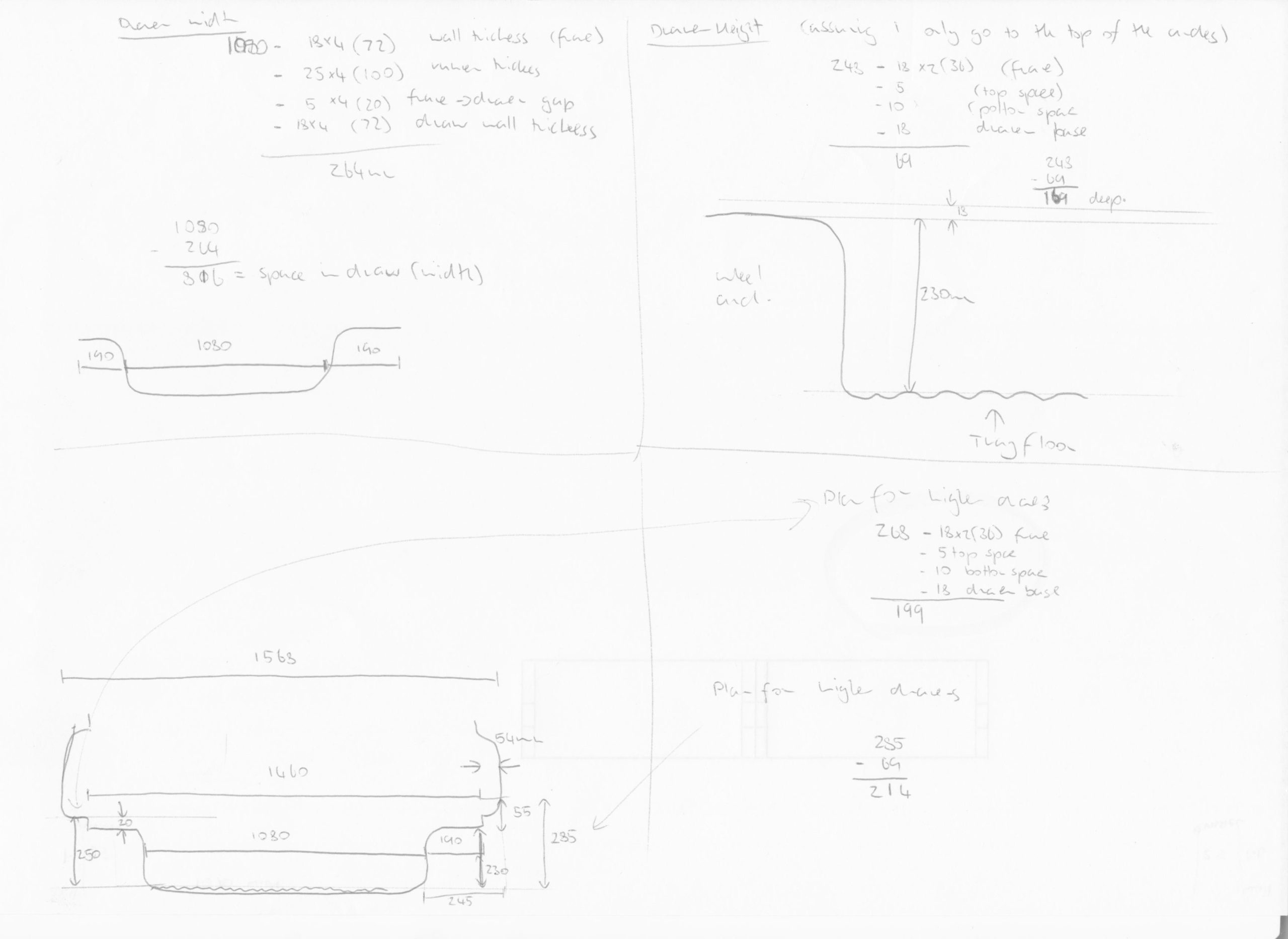
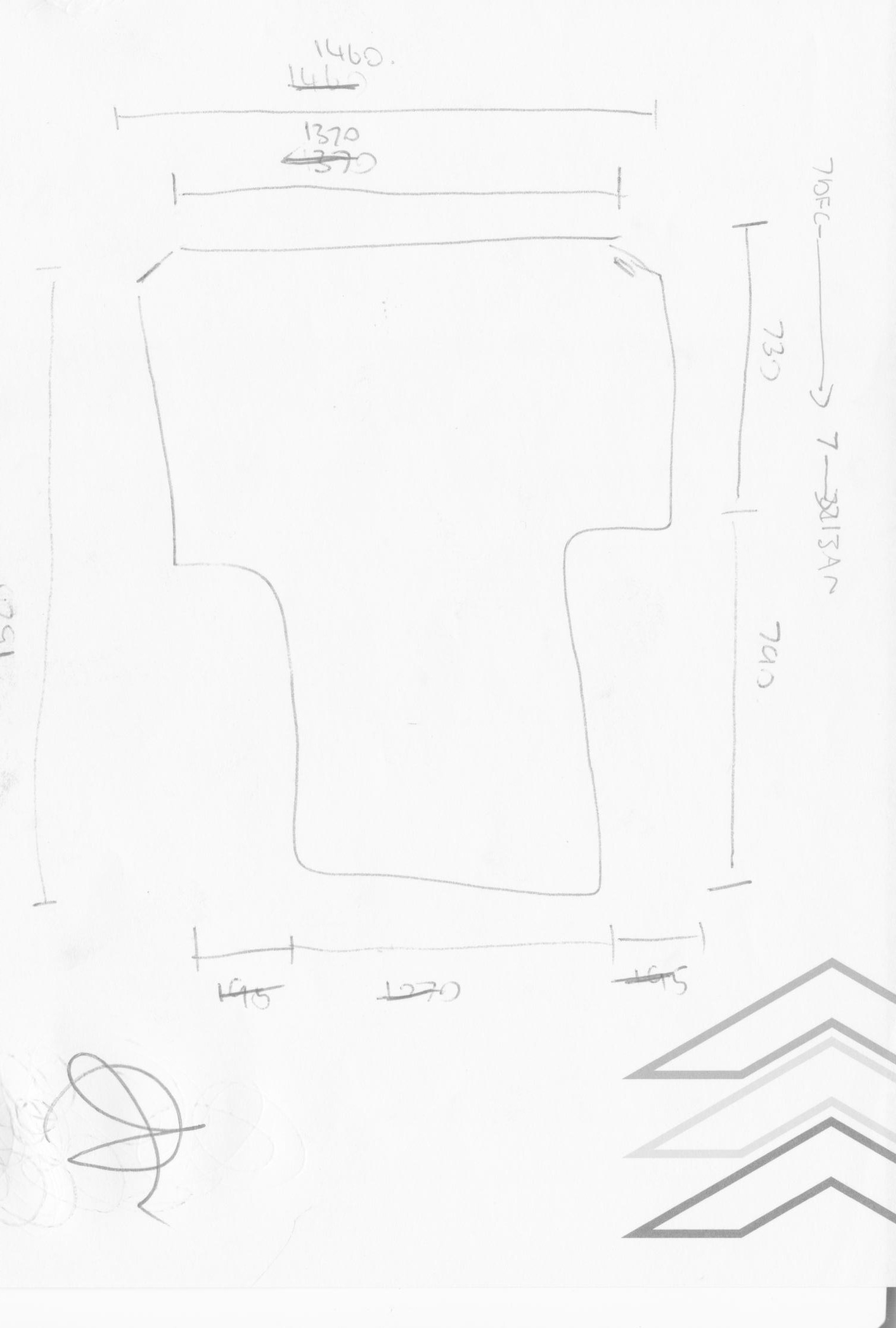
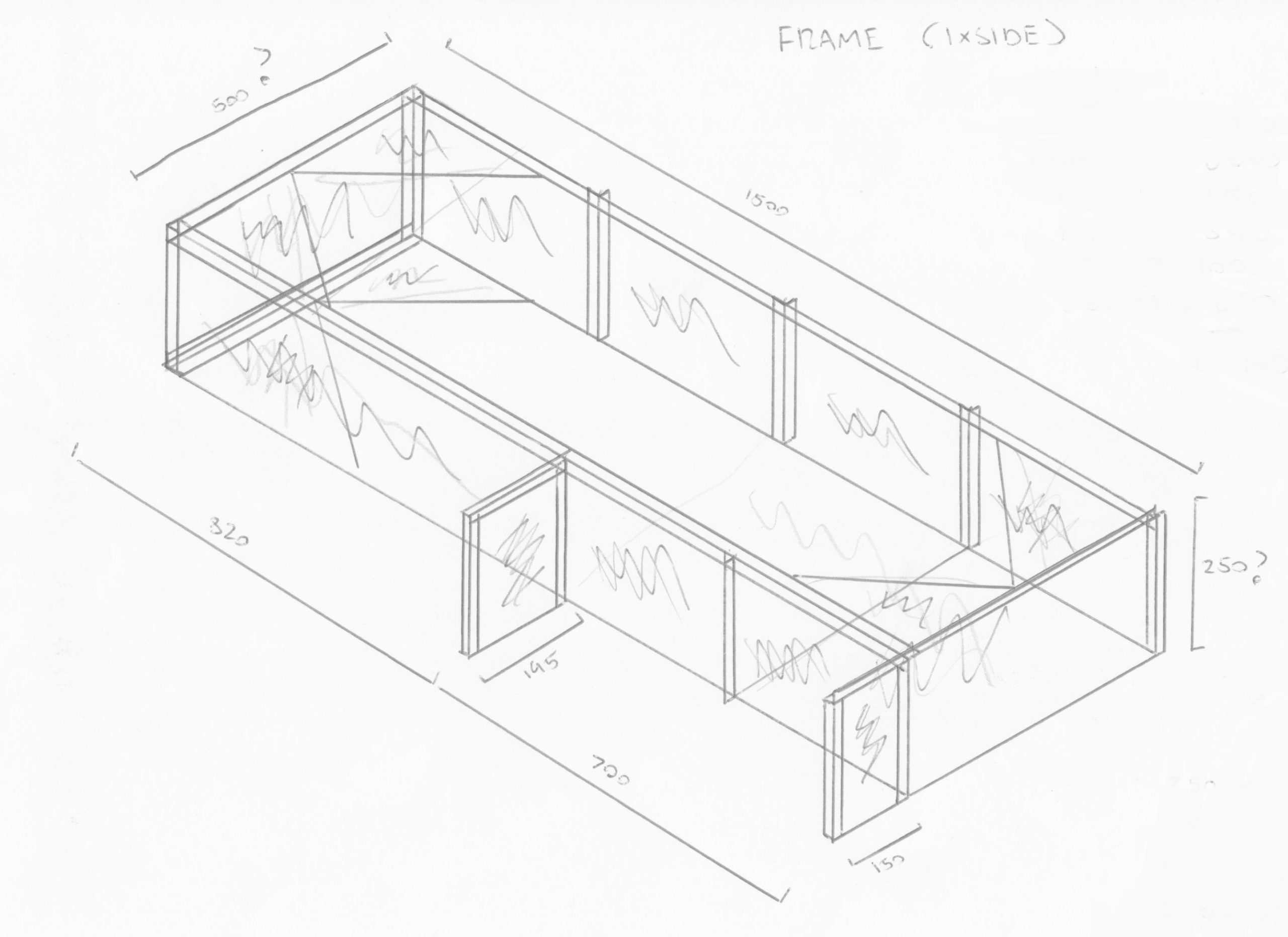
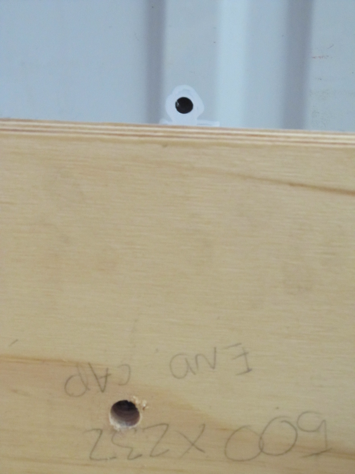
The back of any style-side tray tub is a pretty curvaceous landscape. So start by getting a really good understanding of it, and how you can make best use of it – The object here is to identify the largest cubic shape you can fit into your tray – but don’t worry about all of the curvy bits that are left out, since its your build, you’ll turn them into usable space too! Below is how I did this; If you have a 2007-2009 Ford Dual-cab PJ Ranger – I’ve just saved you some sketching and measuring time!
Figuring out what you want.
Before I go on and describe what I did, here are a few prompts to get you thinking about about what you want:
- What materials do you want to use? I ended up using 19mm ply wood for my drawers because it was cost-effective and strong, but there are trade-offs. 19mm ply was also heavy and susceptible to water damage – there was nothing I could to about the weight but to offset the risk of water damage I lacquered every piece of ply I used (before screwing them together) to limit opportunities for water absorption. I seriously considered making the drawers out of 13mm RHS or 19mm angle steel and aluminium checker-plate – this was also strong, but only as strong as my welding, which was still developing in 2011 – I was also worried about it rattling and rubbing on my tray, potentially creating opportunities for rust. It was also more expensive that ply wood and about the same weight.
- How will you secure it in the back of the ute? if you’re lucky there will be a few tie-down points that you can incorporate into your build to secure your drawers in, another option is to make your own fixing points – I found that a lot of builds were bolted to the floor of the tray – which concerned me about water getting in and rust – I settled for a combination of existing tie-down points and the insertion of rivet-nuts into the rear wall of my tray that I could bolt the drawers to. The rivet-nuts still mean there’s holes drilled in my tray, but they’re higher up, and not somewhere where moisture could sit.
- Do you want a void behind your drawers? While I don’t have one; a good idea I came across was deliberately leaving a void at the back of a drawer to accommodate a dual battery system (out of the heat of the engine compartment).
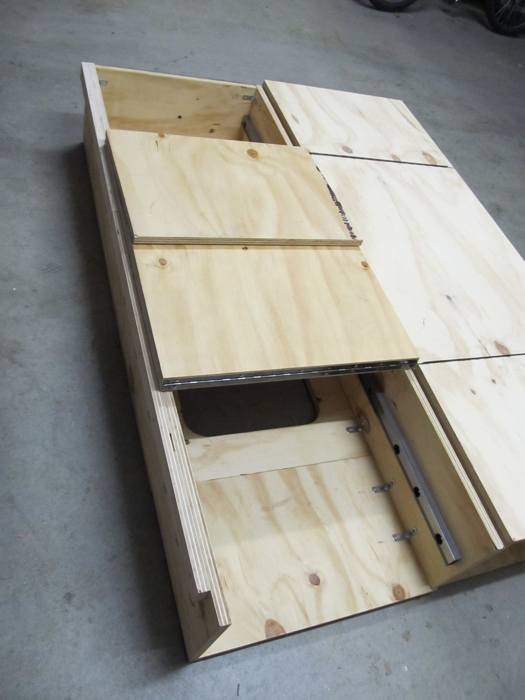
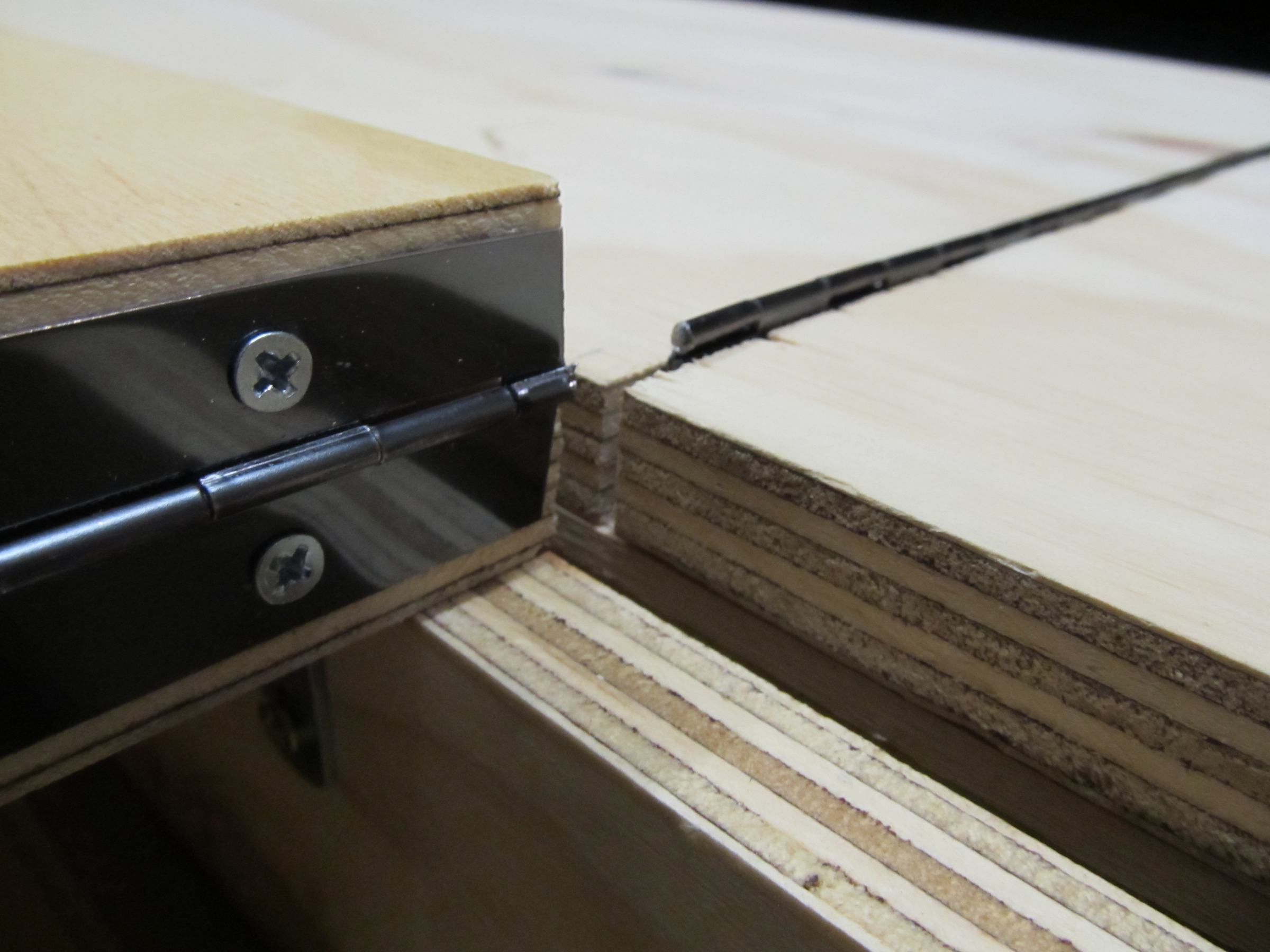
- Do you want to be able to get into the drawers without sliding them out? I piano hinged a lot of the deck above my drawers to give me additional options to stack and access the drawers – this also helps with bolting/unbolting the drawers from the back wall of the ute tray without having to crawl into a confined space.
- Are you going to miss the space that the drawers consume? Obviously I overcame this my making my drawers modular, and as happens; for most of the last decade, unless I’ve gone camping I’ve usually only had one half of the drawers in at any one time, this gives me the ability to carry more bulky items in the ute tray – If my drawers were permanent fixtures, or very hard to remove, I would have needed, and missed, that floor-to -ceiling space quite regularly.
My Build. Part 1 – The Frame.
I’ll let the following pictures to the talking, and give additional explanation as necessary.
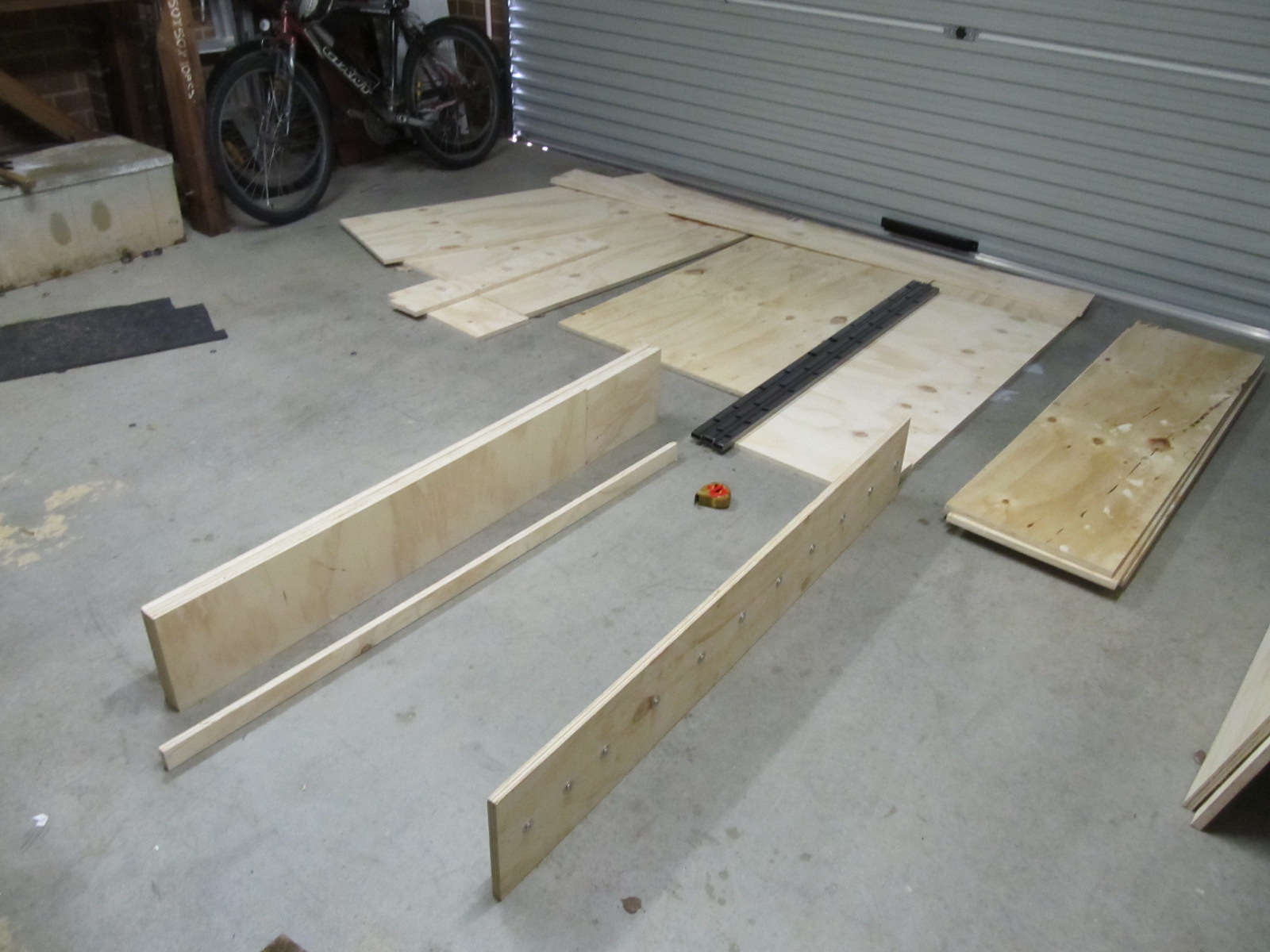
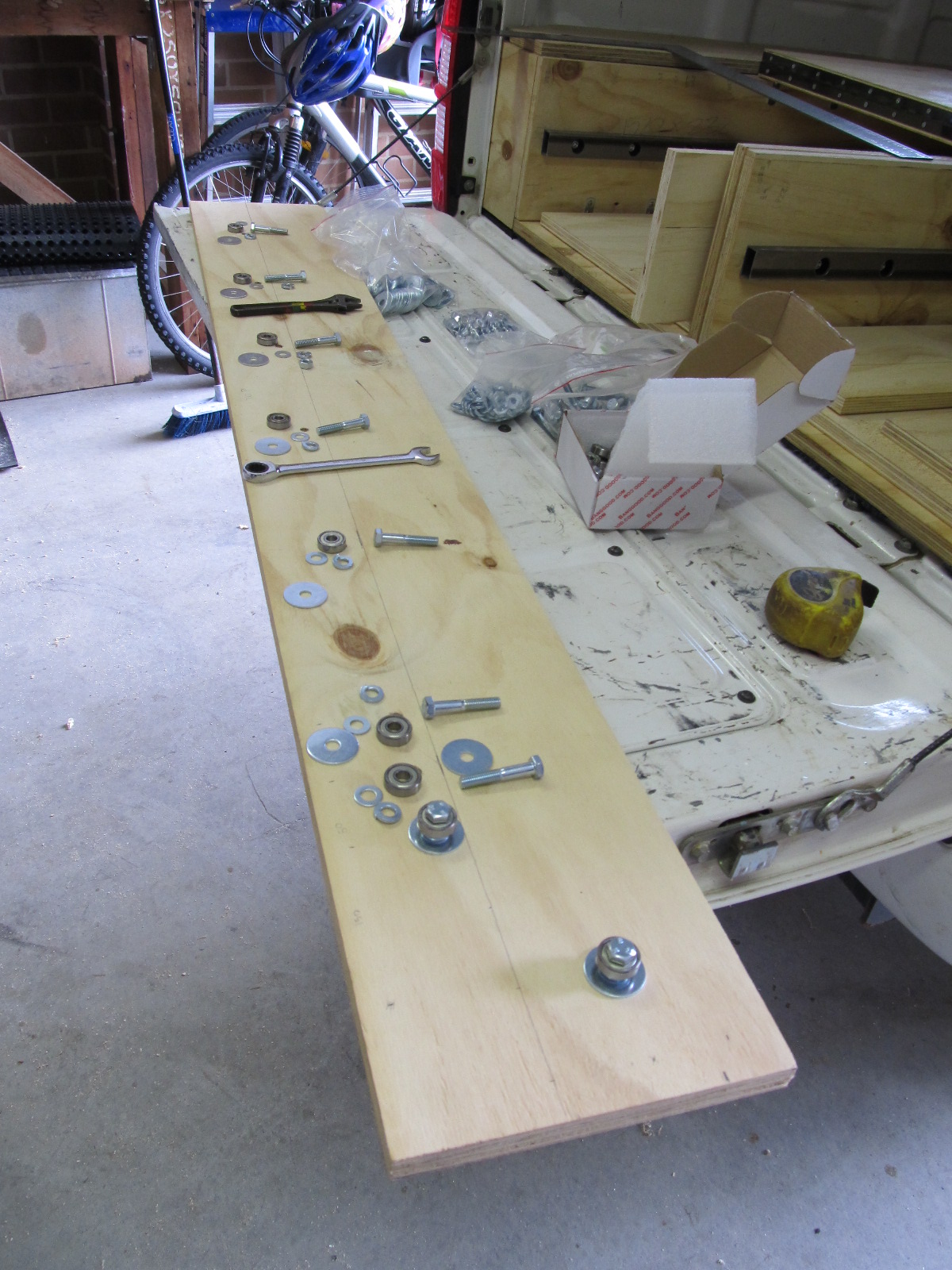
First up was some bulk cutting, don’t worry this will all take shape very soon
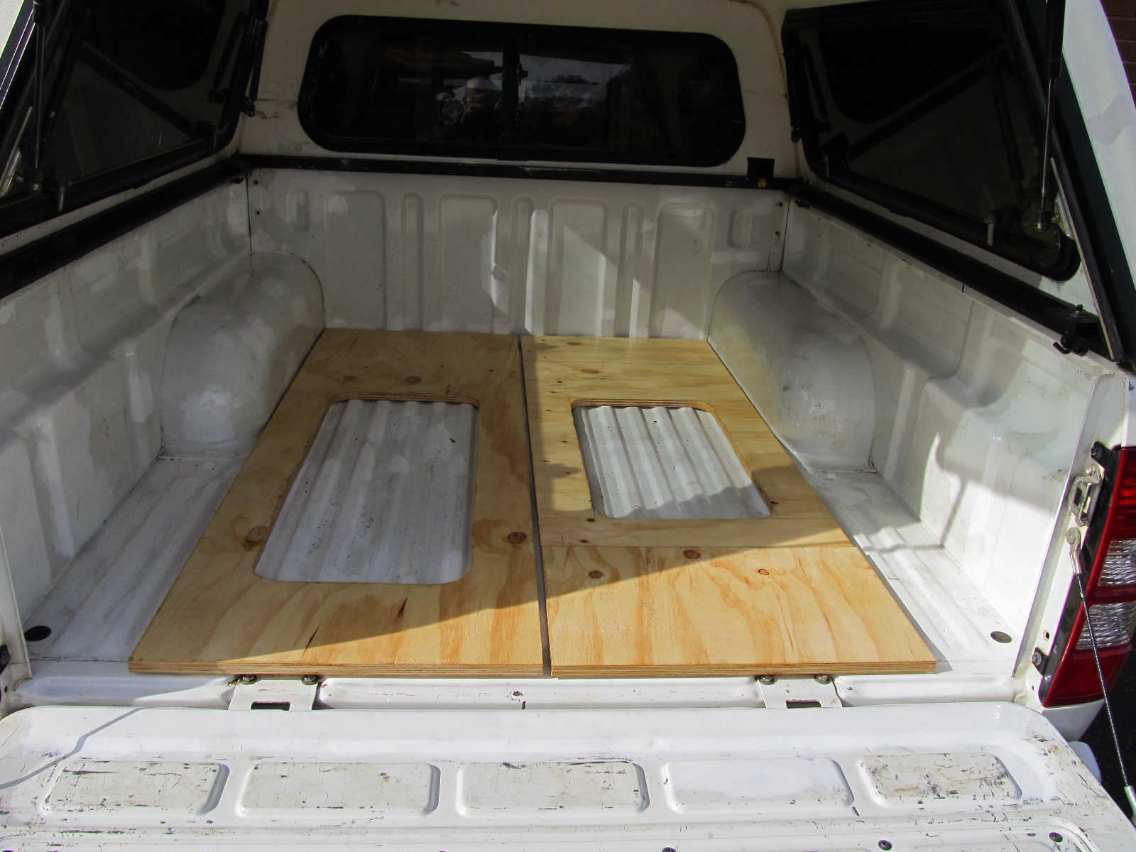
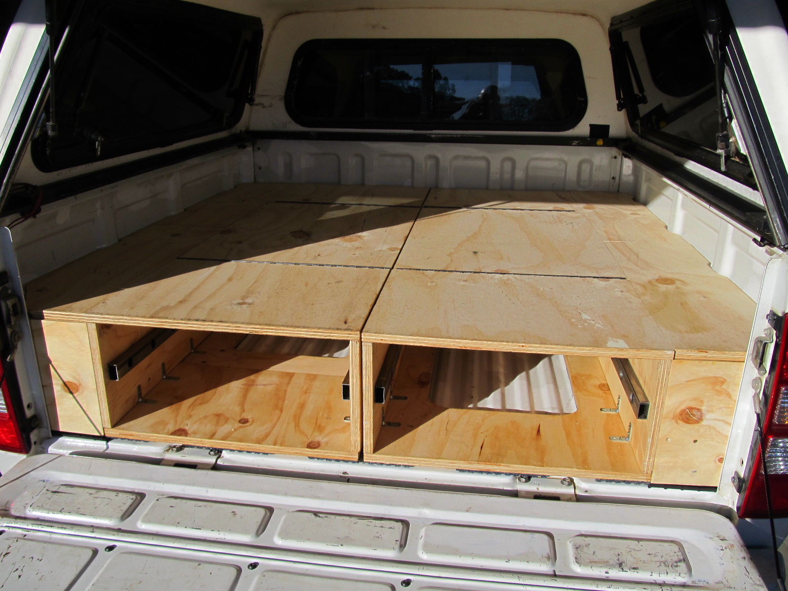
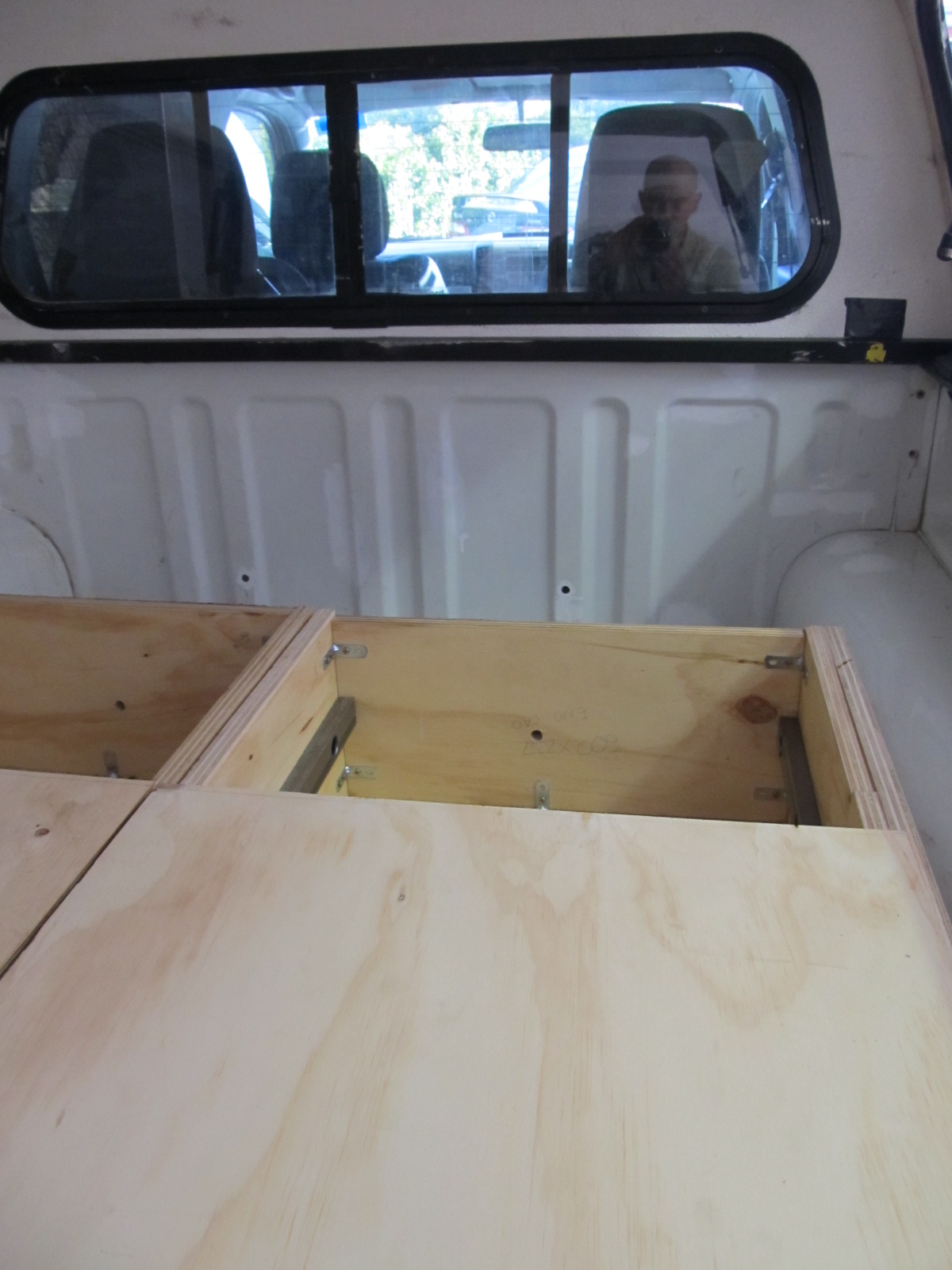
Now we start placing bits into the back of the ute.
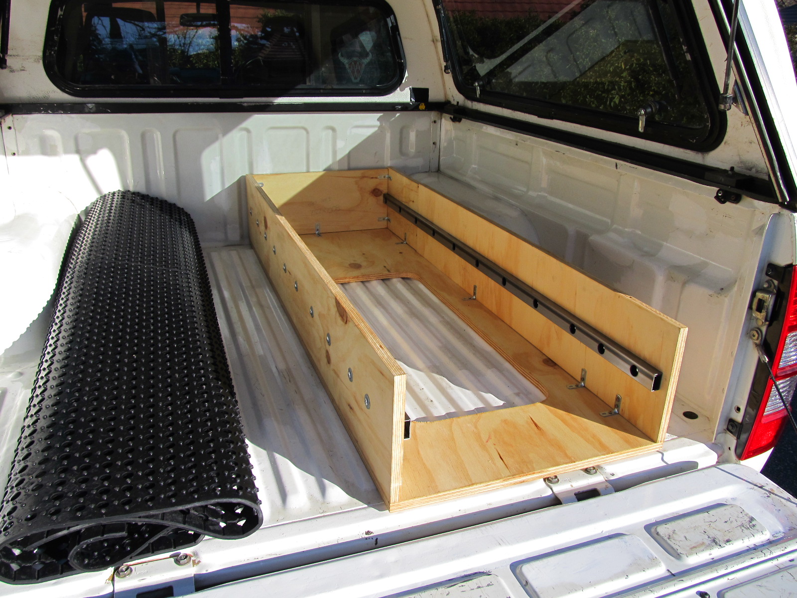
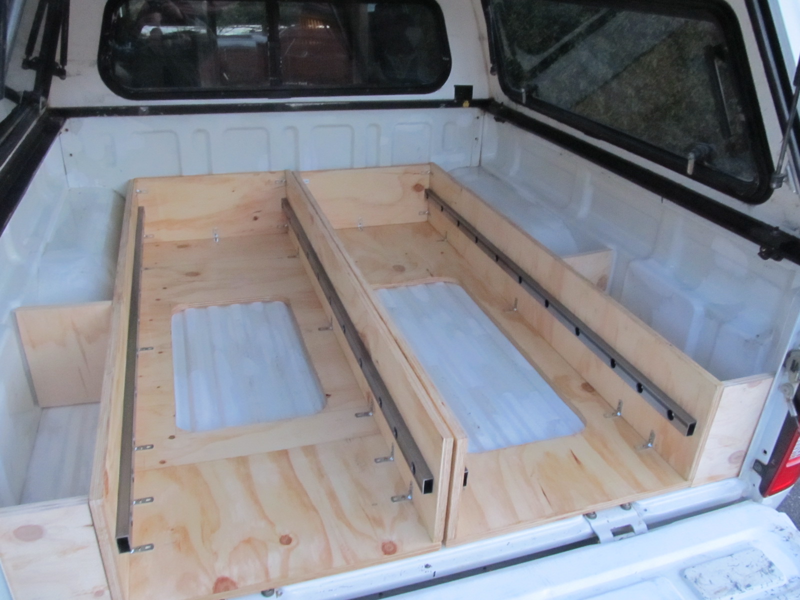
Now that the base and back of the drawer frames, which constitutes the main components coming into contact with the ute tray, are complete I put strips of marine carpet on the surfaces that contact the ute tray. This is to look after the paint on the ute tray as well as to deaden vibration. The I attached this with 3M spray on contact adhesive – it hasn’t moved in 10 years!
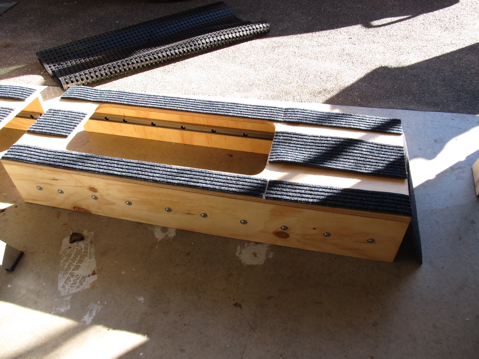
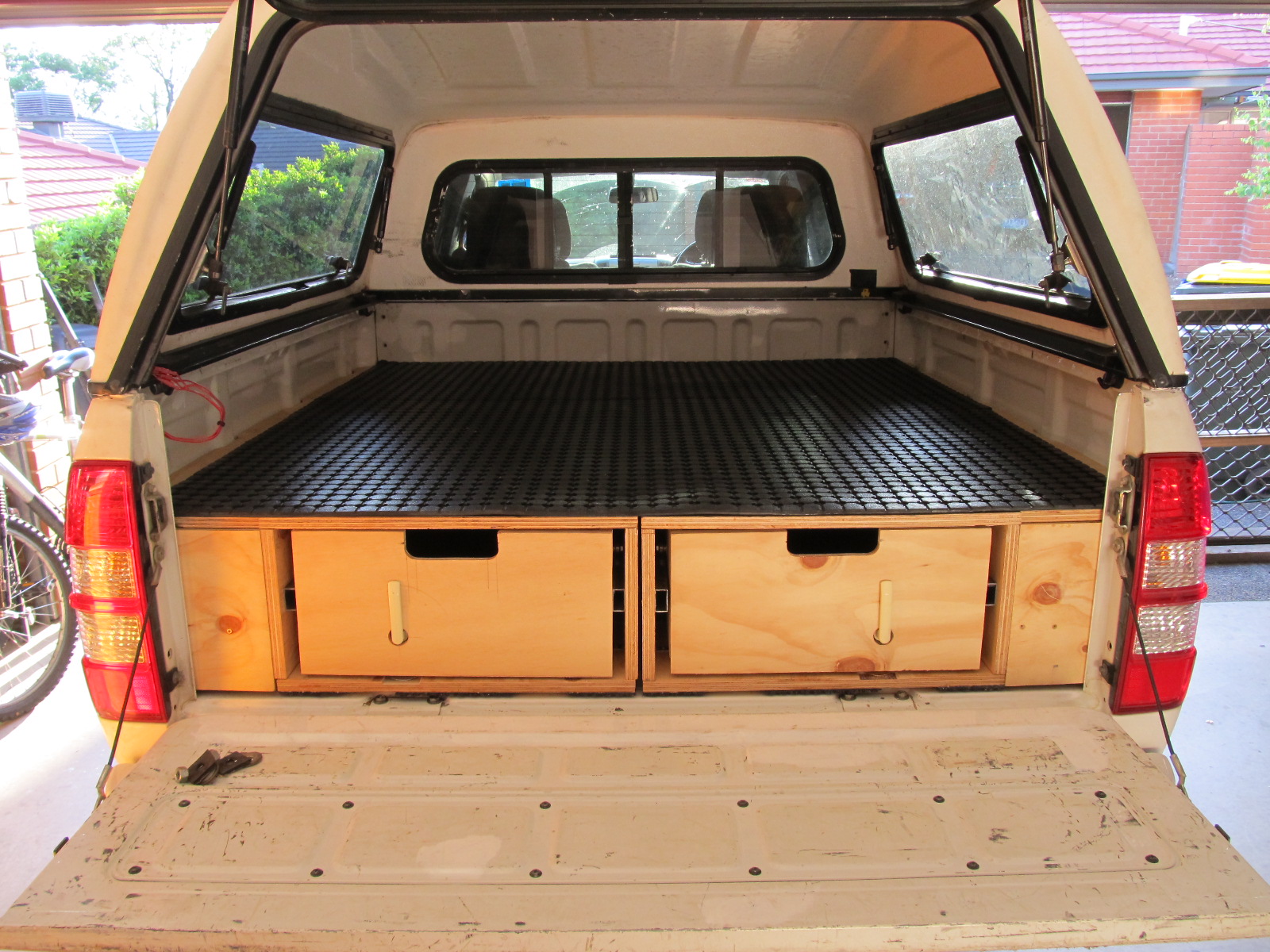
Many custom made drawers are completely covered in synthetic carpet, and I am yet to understand why. I consider it a means of trapping dirt so I gave it a miss, instead opting for a removable rubber ute tray liner to cover the top of the drawers.
The next step is to start putting the deck on to the top of the drawers, this deck will be split into a number of components.
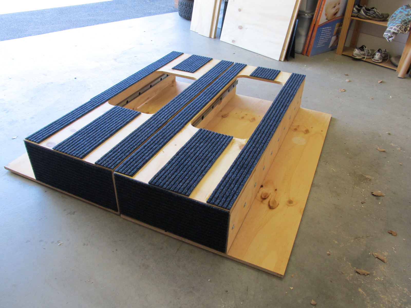
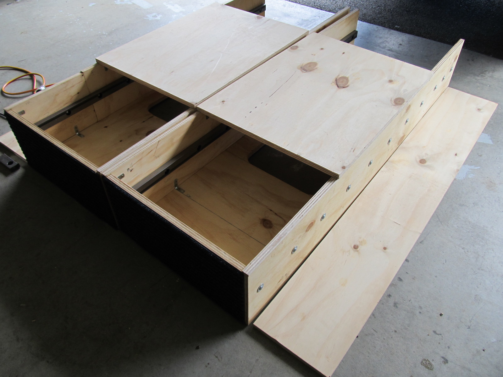
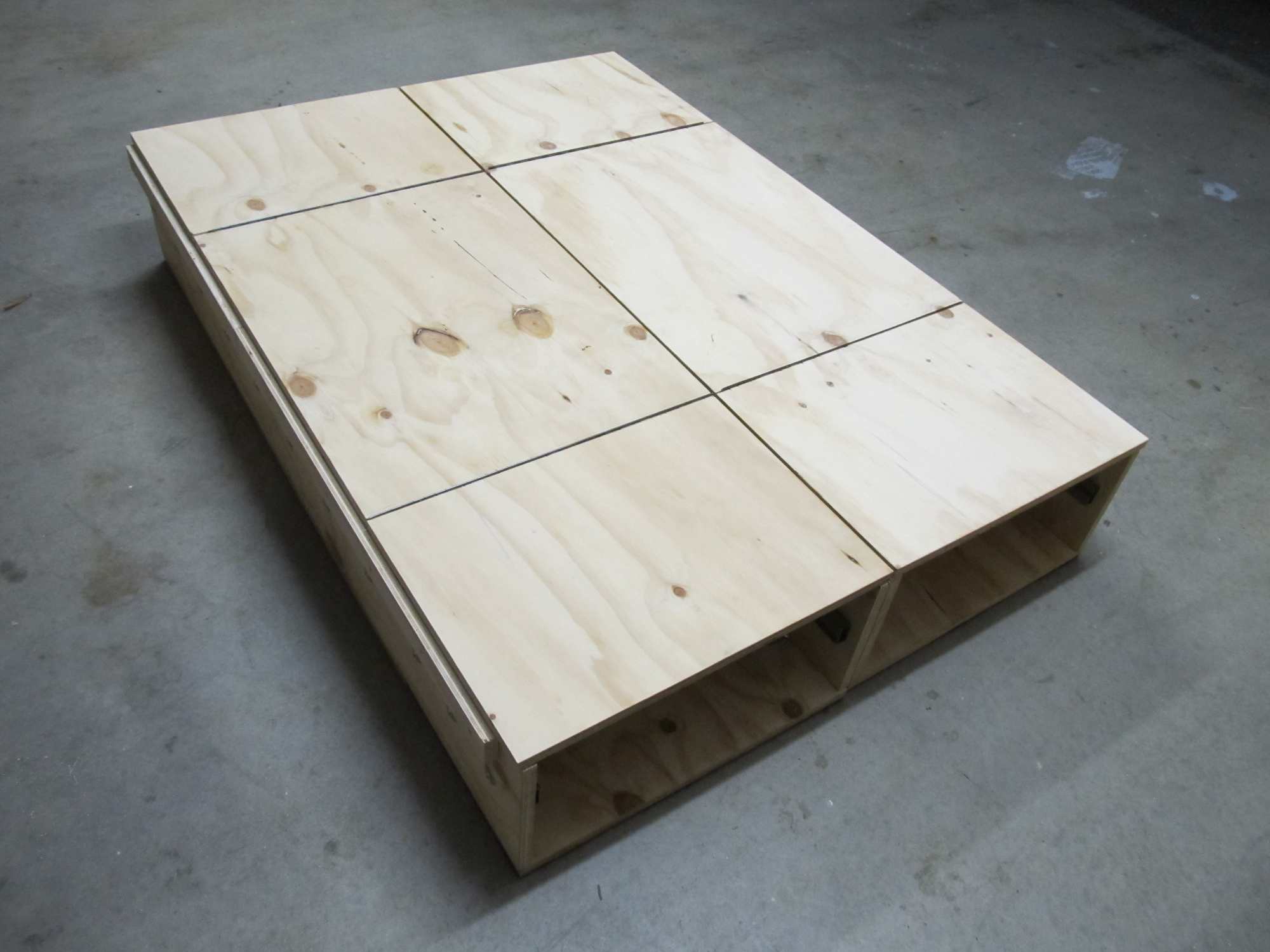
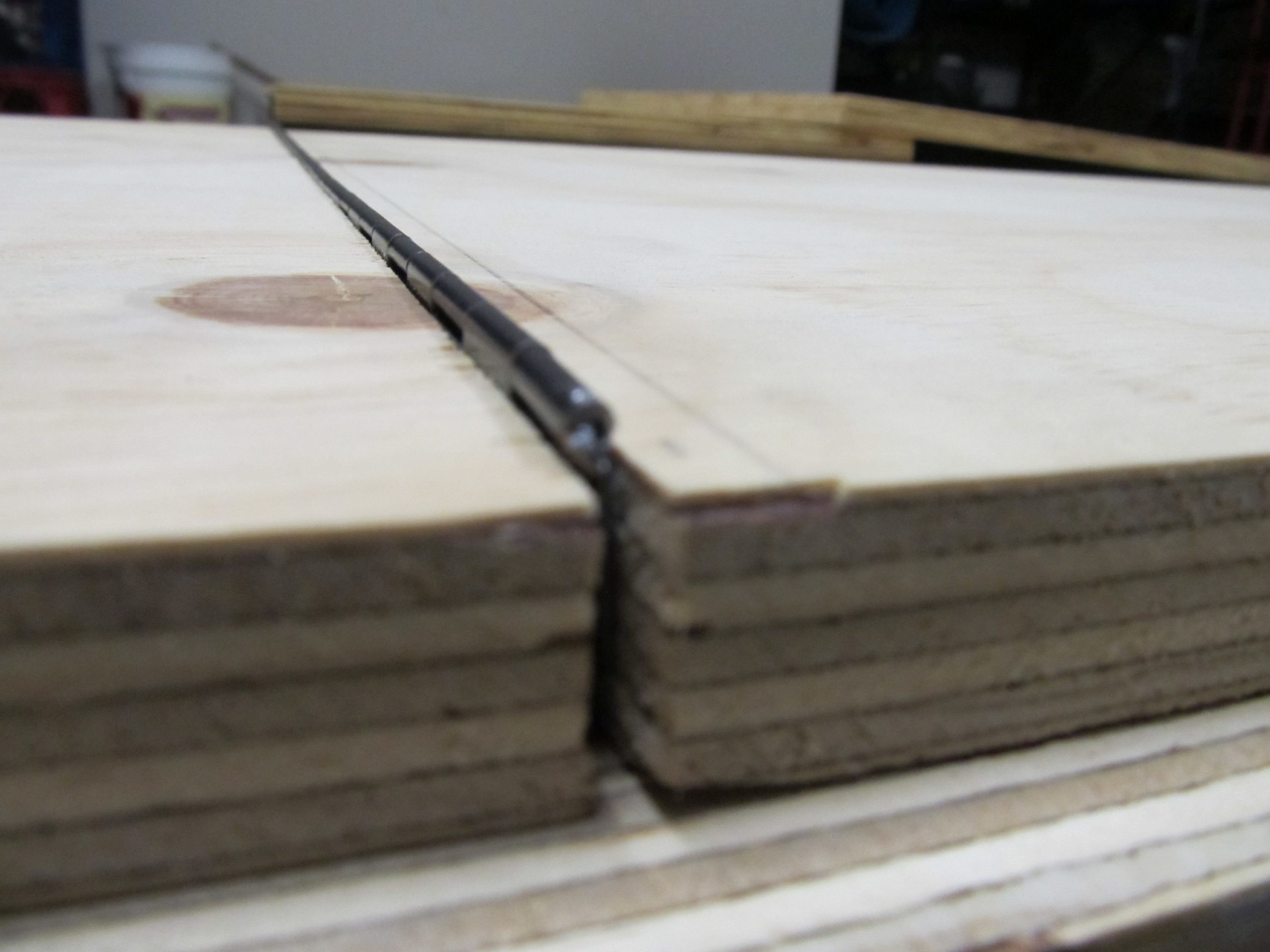
A long section off ply is screwed to the outer sides of the drawers, this will create a ledge for the inner edge of the ‘wings’ of the deck to rest on, while the outer edge of the wings will rest on a ledge on the inside of the style-side tray (more on them later).
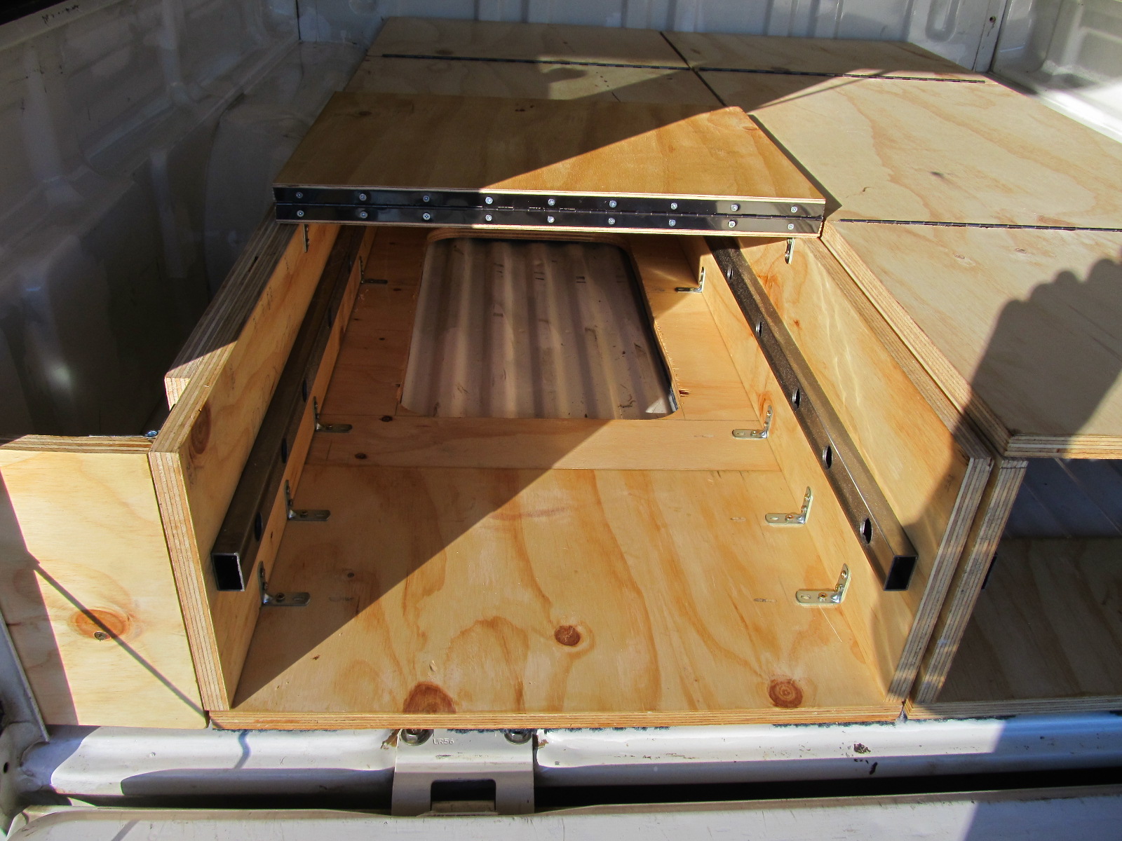
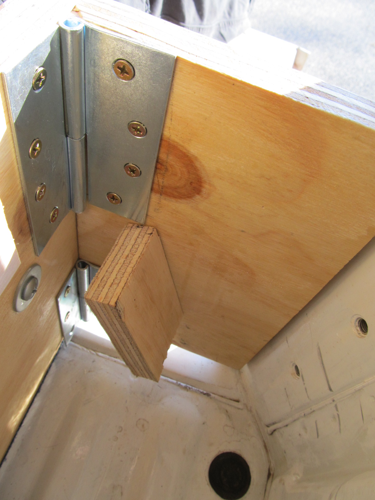
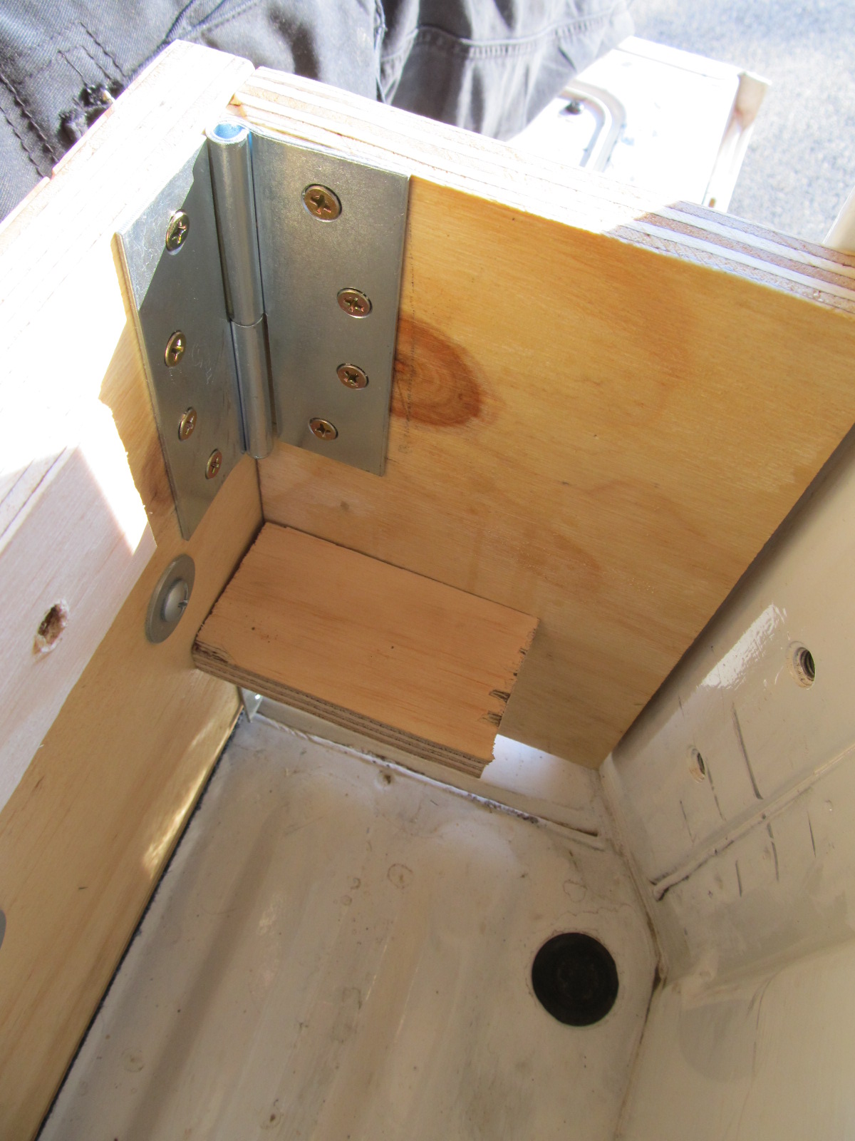
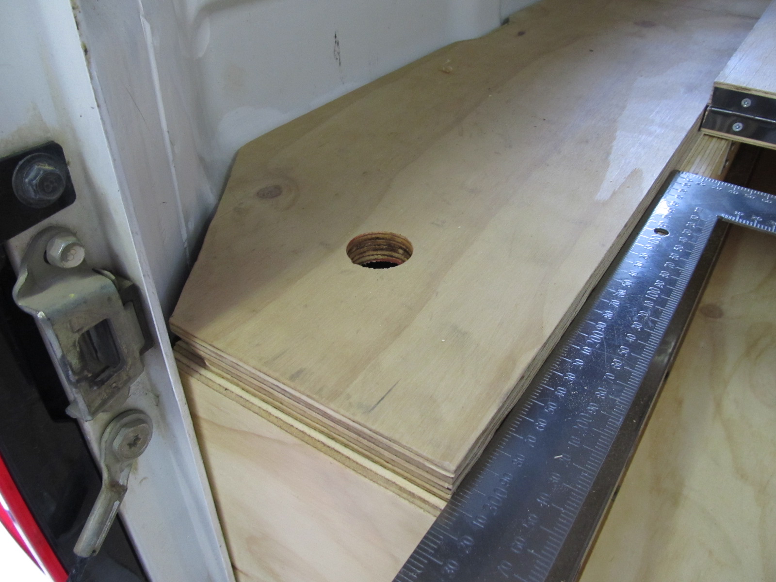
The blanking plate at the front left of the above picture serves two purposes: Firstly it completes the enclosed space to the sides of the drawers, which will be accessible from the top and creates an excellent usable space, and secondly it is of structural importance because it stops the drawers from moving to the left and right in the ute tray.
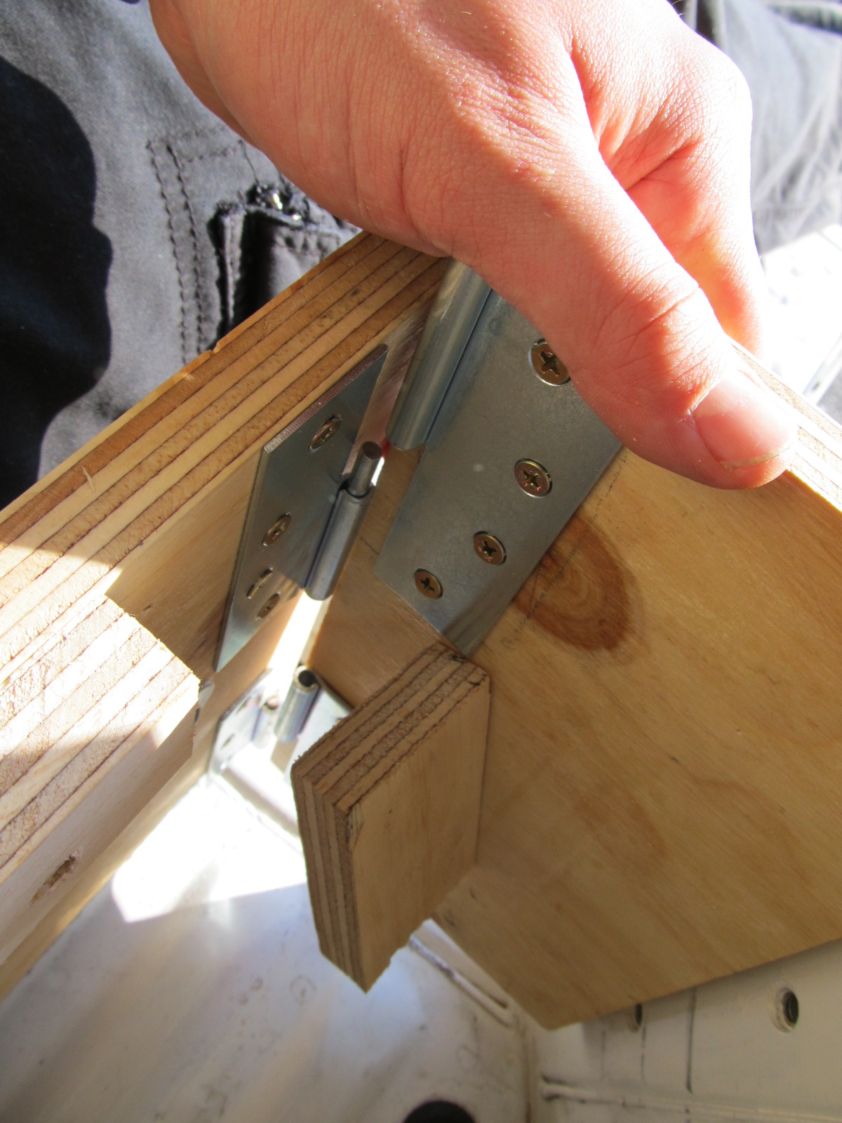
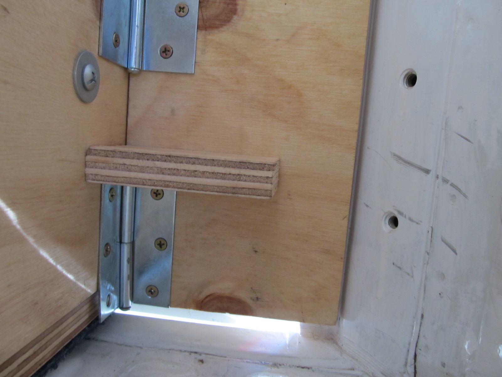
As per the pictures below, the blanking plate is inserted using a lift-off hinge and then a block of ply is swung into place to lock it into place thereby giving the entire drawer system its lateral rigidity in the ute tray. At a later date I added a turn-buckle between the outer edge of the drawer frame and the anchor points on the ute tray (bolt holes) to keep the drawers form shifting toward the center of the ute tray when only one drawer was installed.
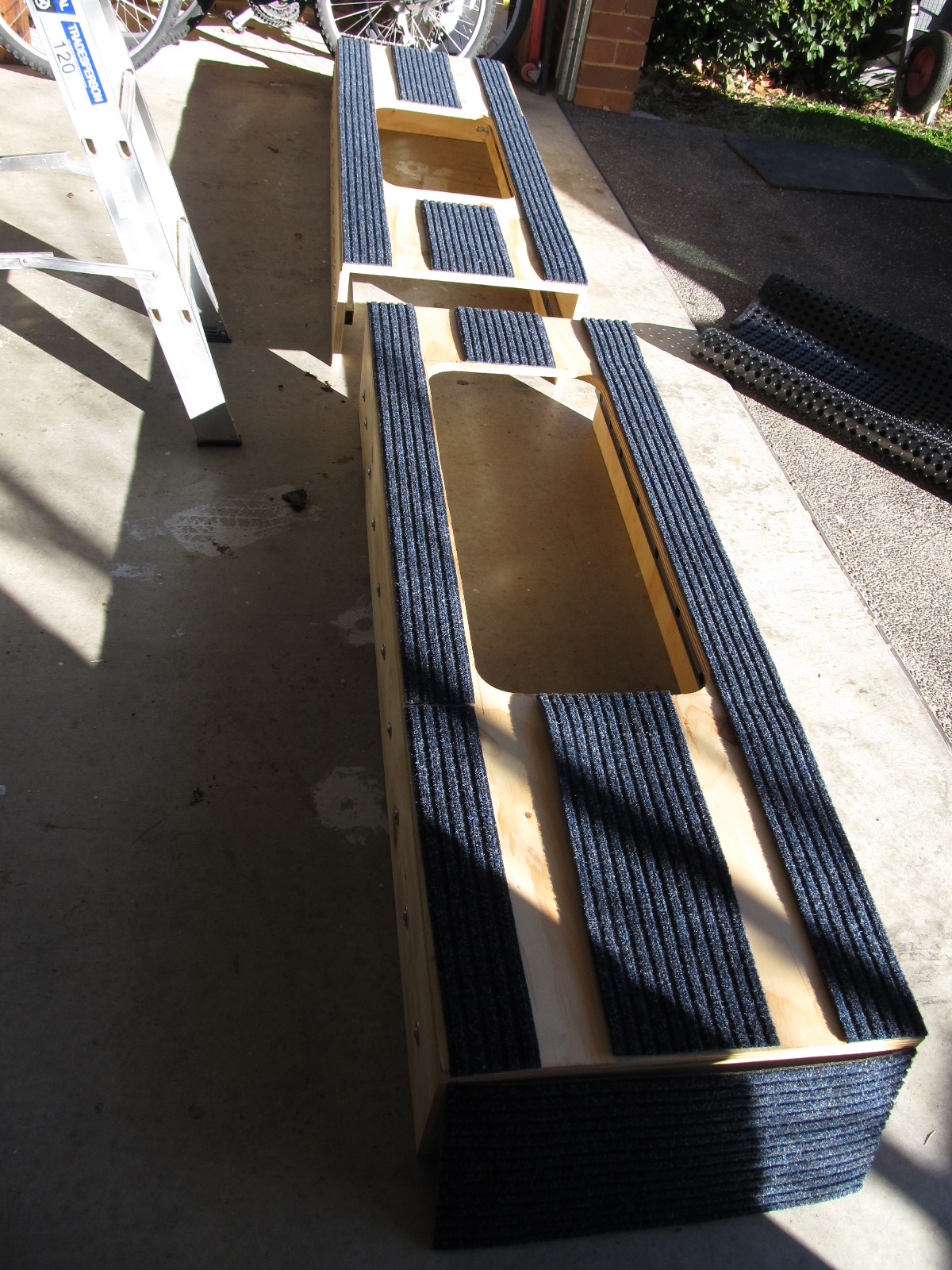
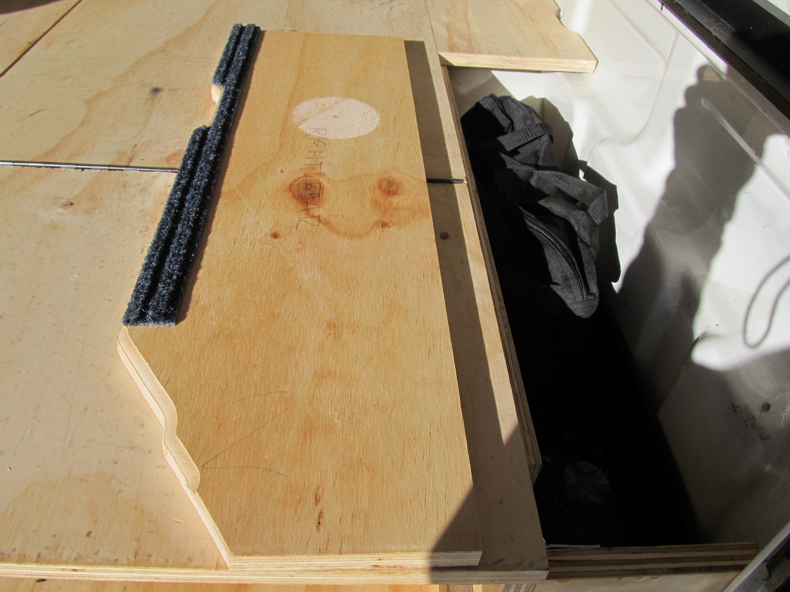
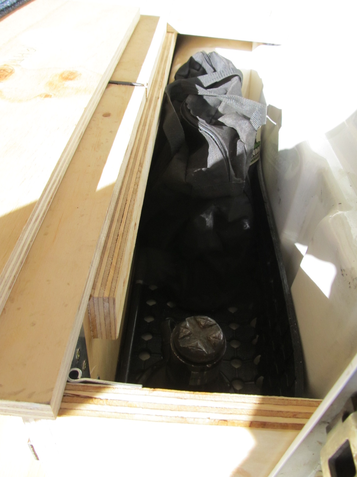
Next I shaped and installed the deck ‘wings.’ This required a bit of work with the router and a little more marine carpet to pad the additional contact point with the ute tray. As you can see this created a sizeable and easily accessible space, in which I now store, tools, jumper leads, jack and handle, and long items such as pipe and umbrellas, since the space goes the full length of the tray (albeit for long thin items that can fit above the wheel arches).
You may note that I ended up foregoing the 190mm blanking plate at the back of this section, (as seen in figure 10) this was to enable the storage of long items and because it was providing no structural value.
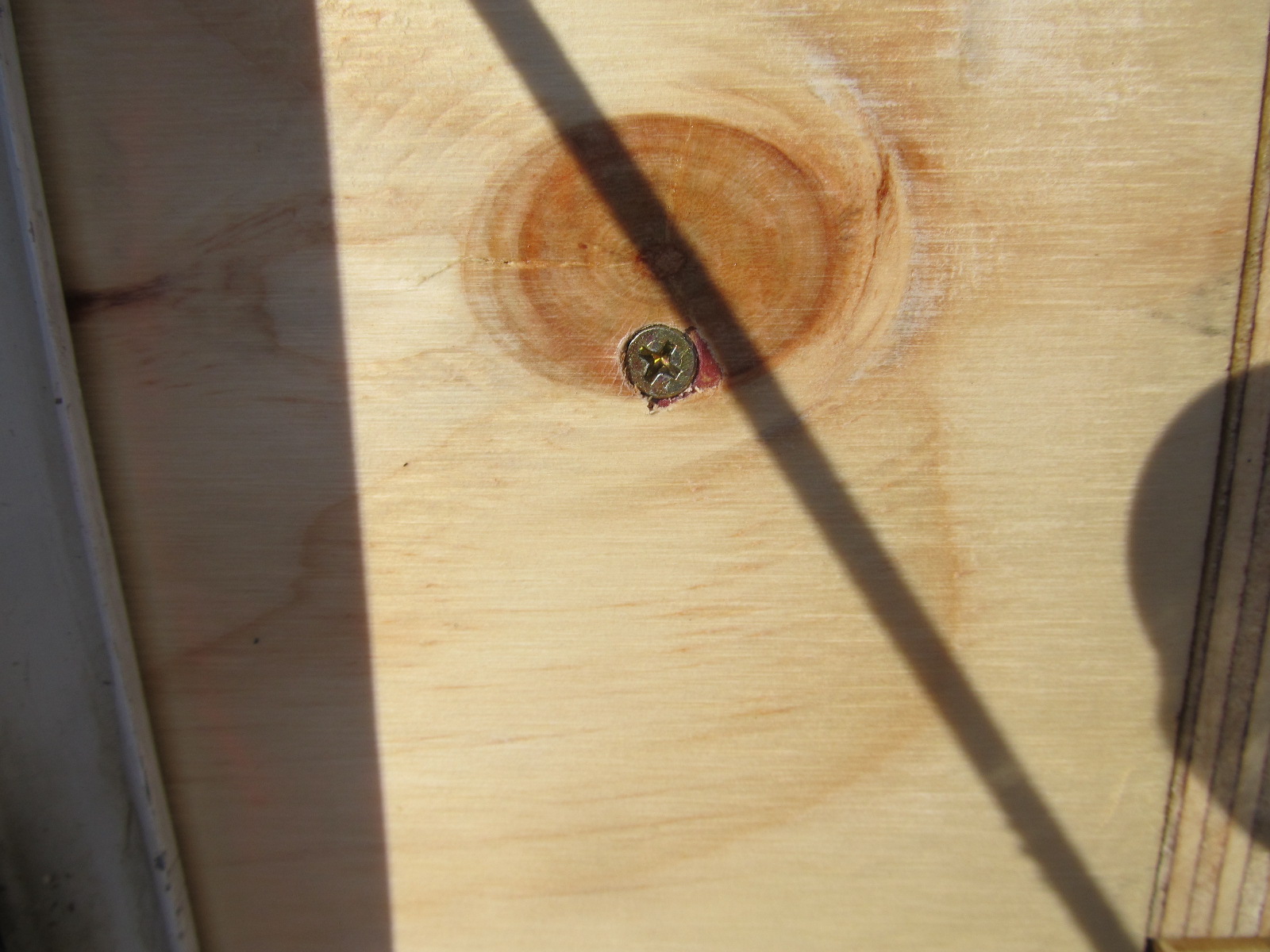
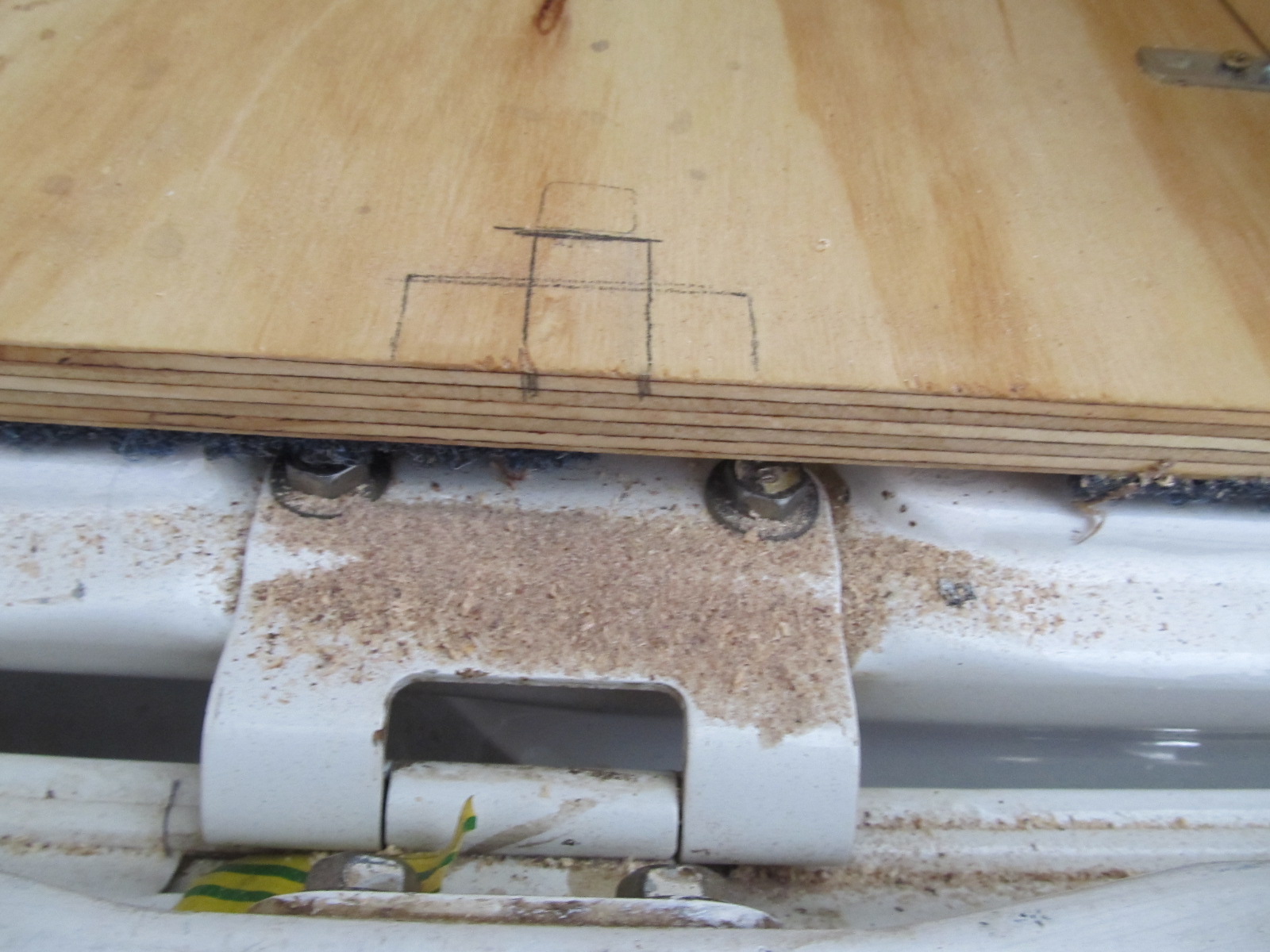
The last job on the frame was to secure them to the back wall of the tray. It was a little nerve racking drilling a hole in a perfectly good tray, and I made sure I painted the holes to inhibit rust.
Because it was almost impossible to work in the space between the back of the cabin and the front of the ute tray (about a 75mm gap that can only be accessed from under the ute) I install rivet-nuts in the two holes you drill in the back of the tray. The rivet nuts can be installed entirely from one side and they’ll enable you’ll be able to just insert and remove a single bolt in order to secure/remove the drawers.
Note that there is a special tool for installing Rivet-Nuts, and you don’t need it! especially if these are going to be the only rivet-nuts you ever install. (just google “how to install rivet-nuts without a dedicated tool” for instructions. You’ll need a nut and a bold (with thread that matches the Rivet-nuts) a washer and two spanners, that’s all!
Two things of not here: having the piano hinged sections at the back of the drawers made this job a lot easier, and is essential for installation/removal of the drawers without having to crawl into the space depicted in figure 32.
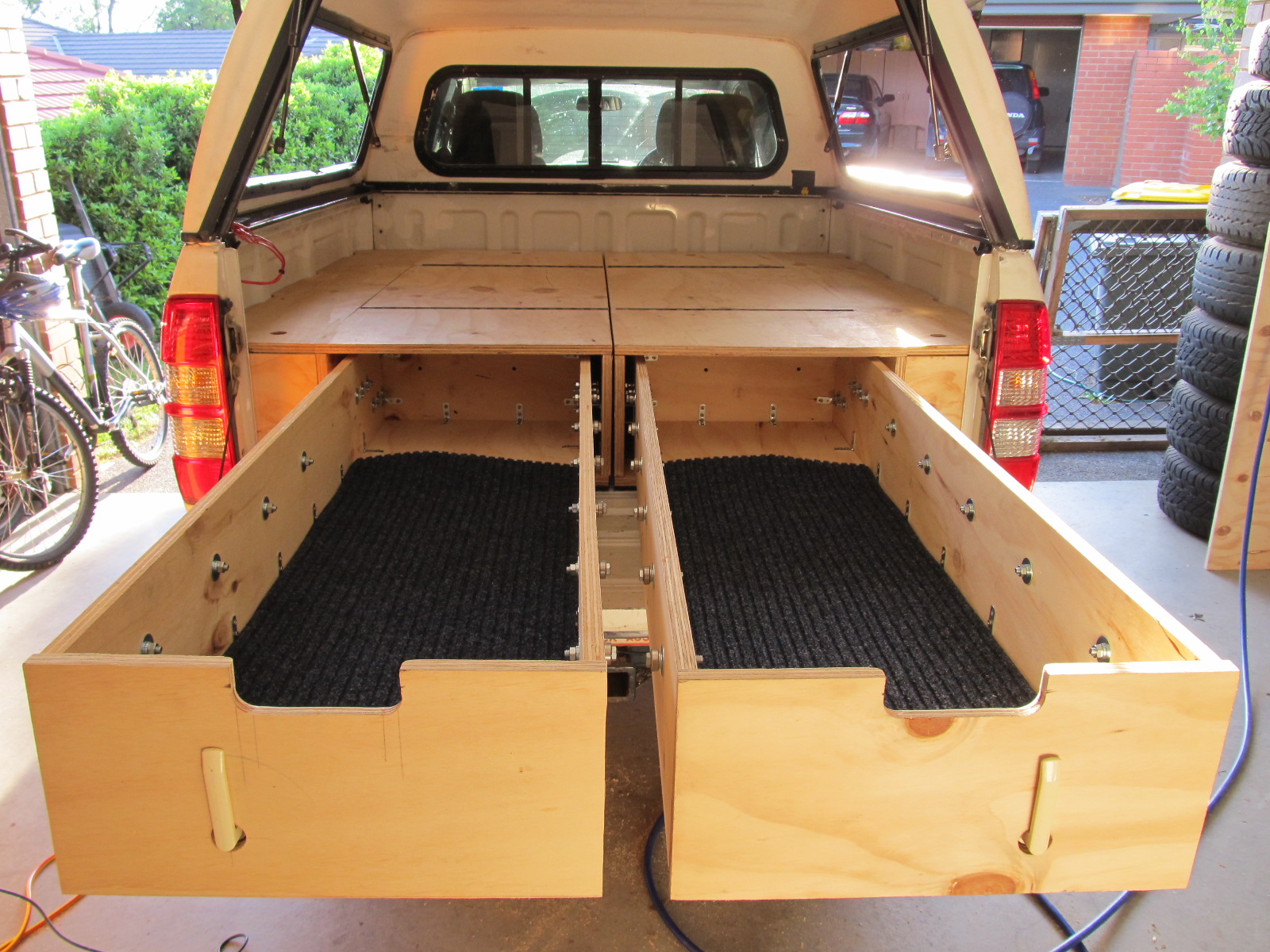
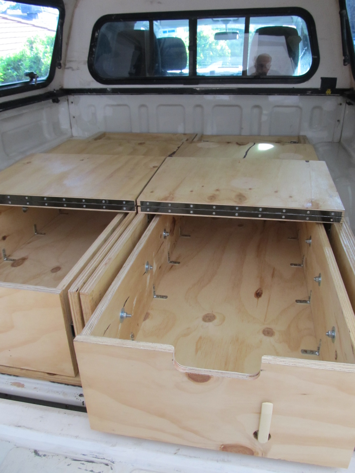
My Build. Part 2 – The Drawers.
Making the drawers was the easy part, they’re essentially an open-top box, and by this point I’d built the frame, which is somewhat more complicated! Making the drawers slide in and out smoothly and lock-in, however; was a little tricky.
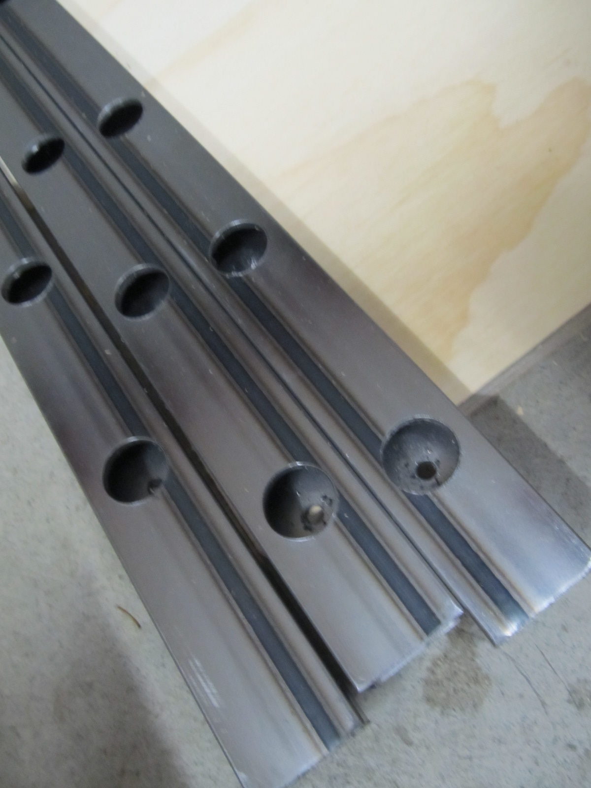
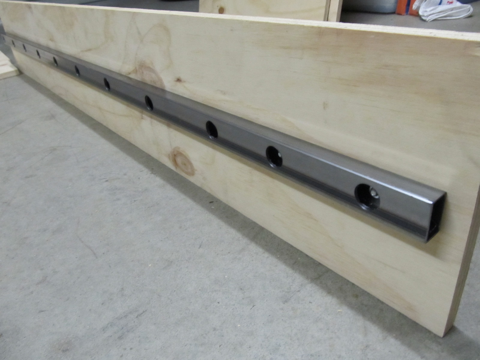
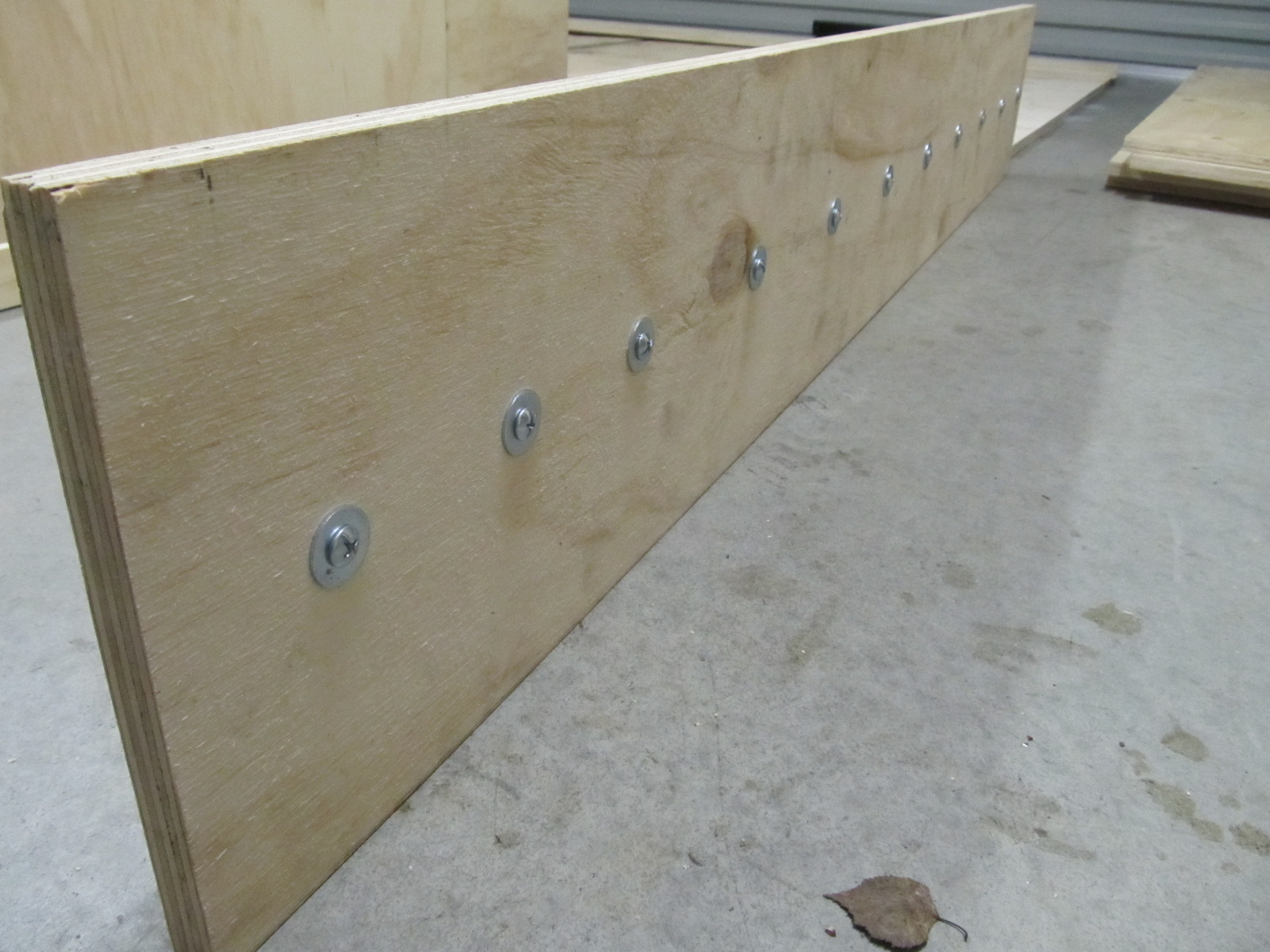
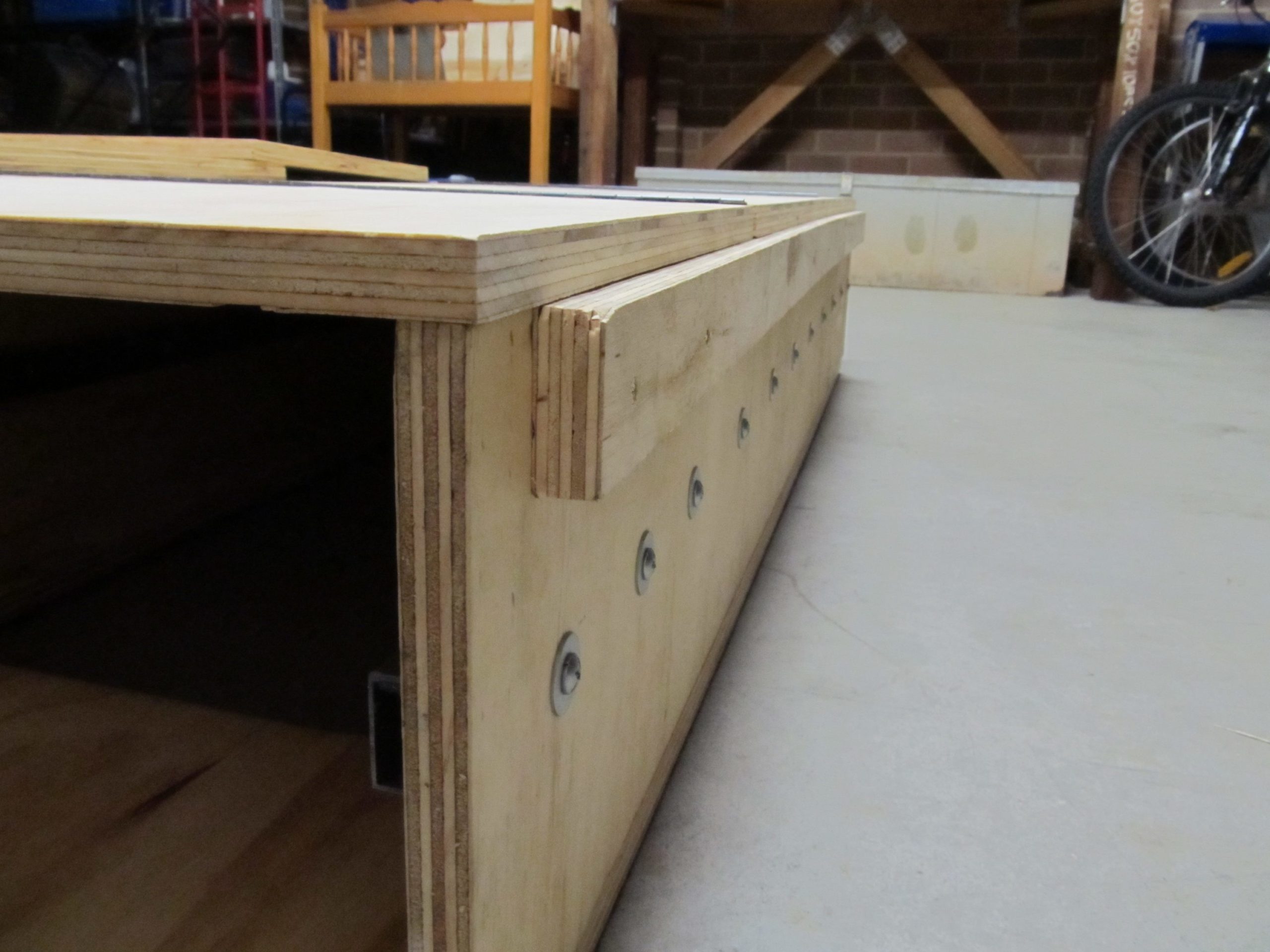
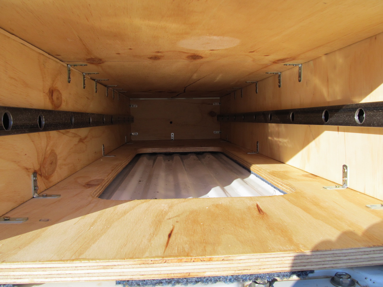
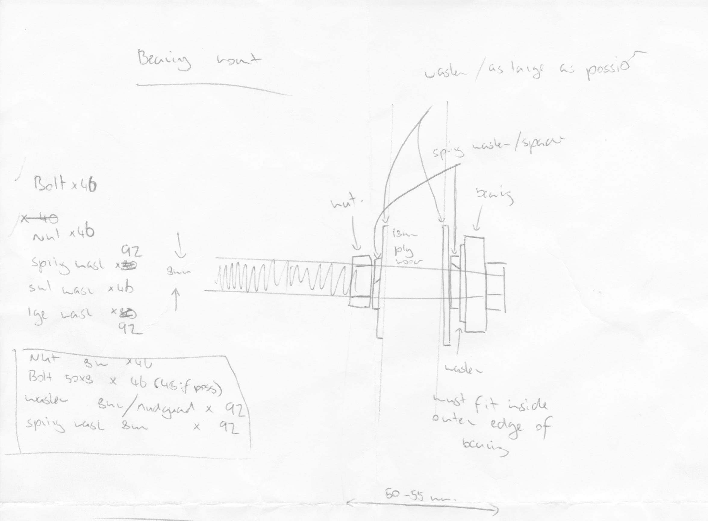
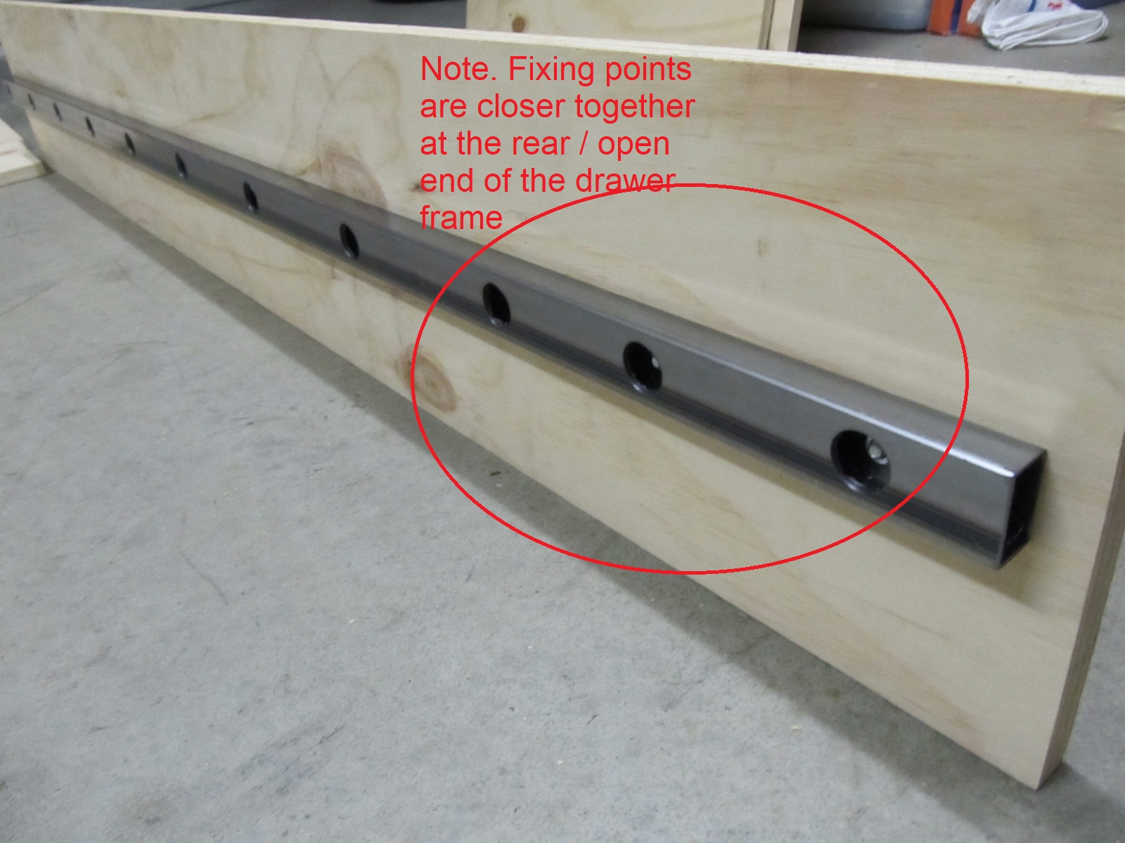
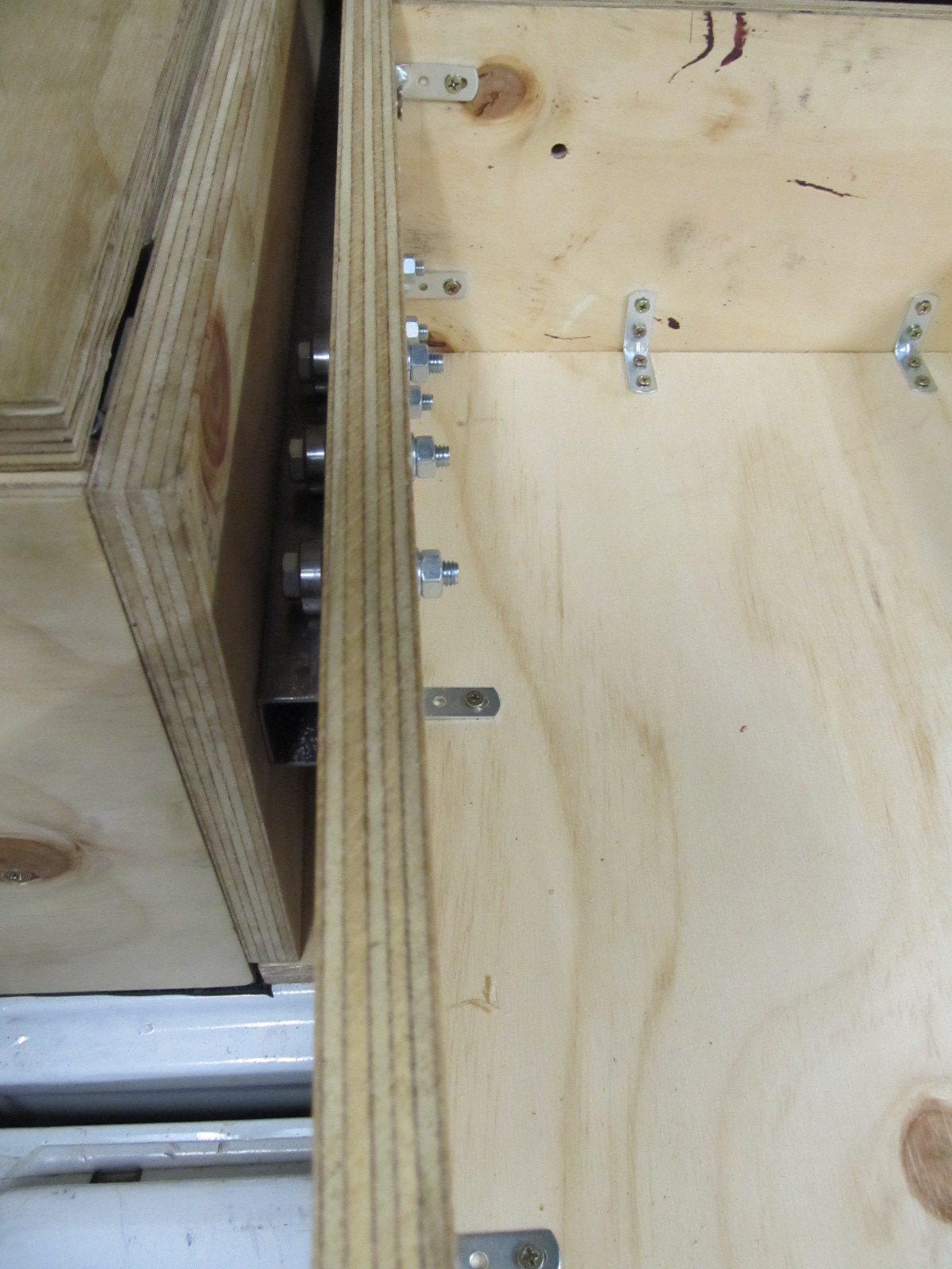
For the drawer runners I used a system of skateboard bearings, bolted to the side of the drawers, that run on top and bottom of the drawer runners (drawer runners pictured in Figures 6 & 7).
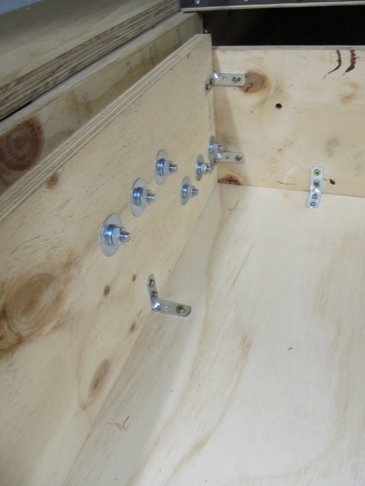
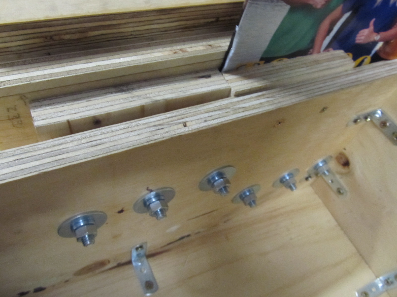
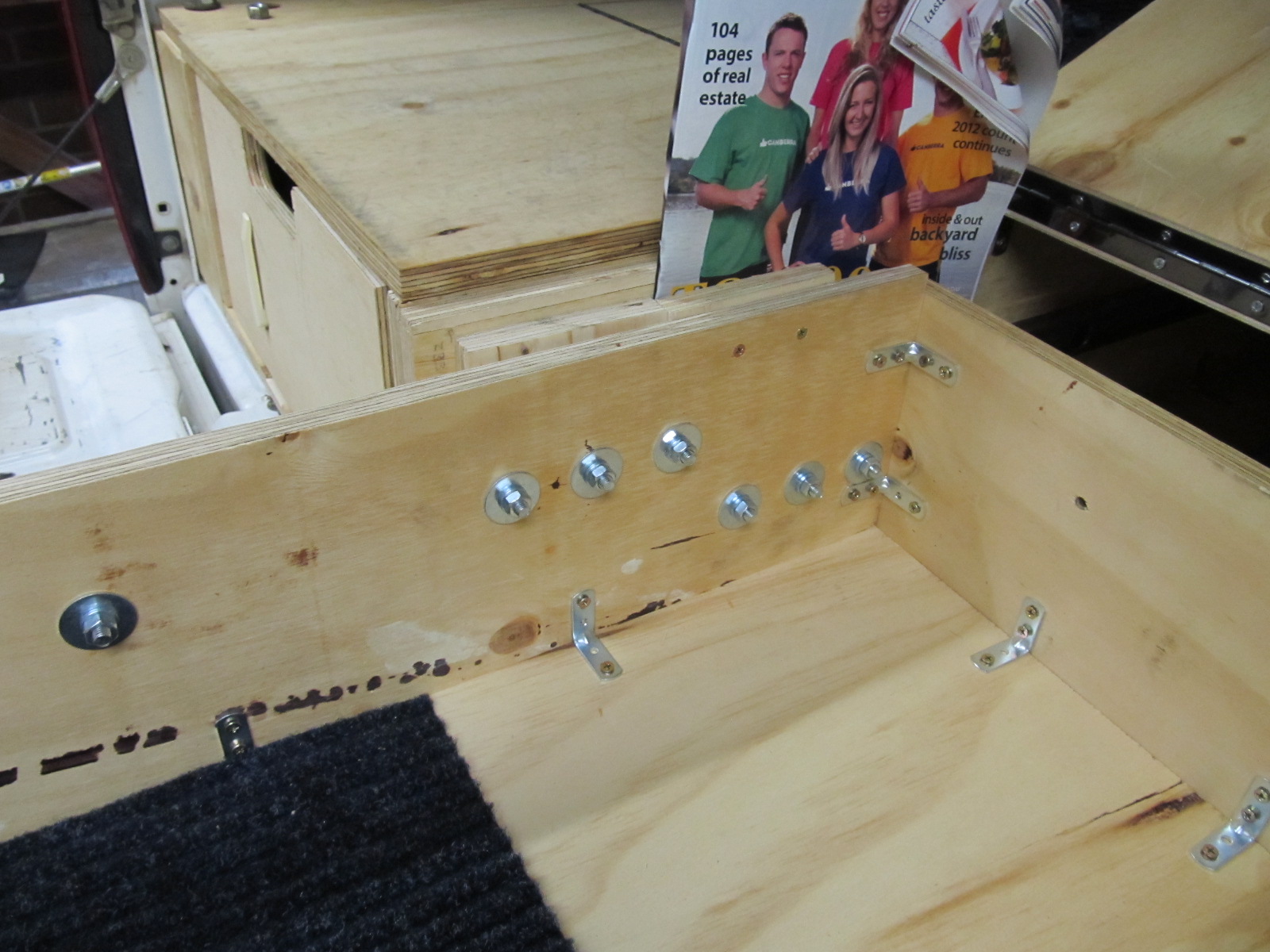
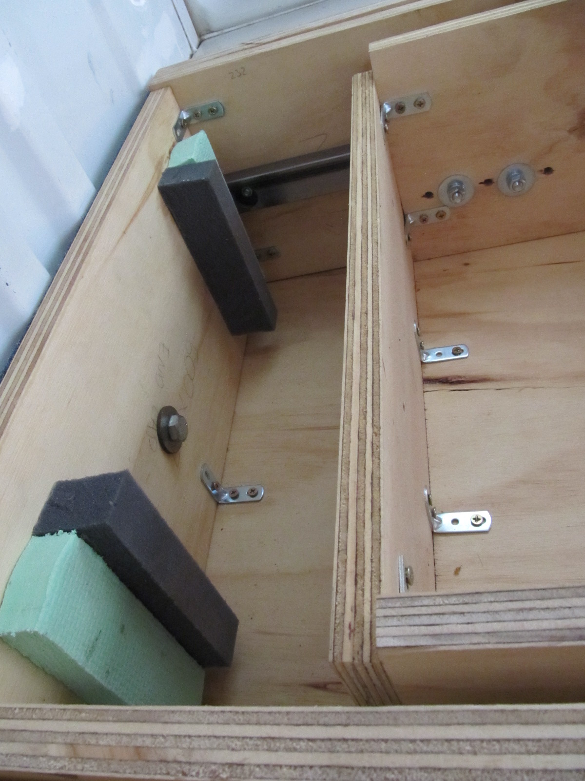
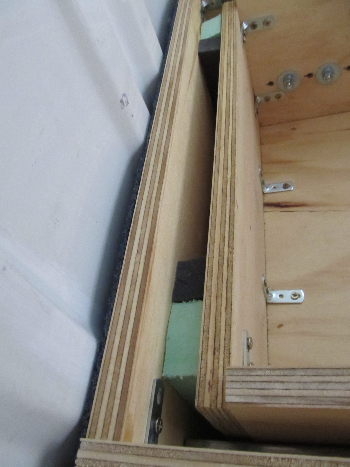
The actual positioning / distribution of the roller beatings on the drawer walls is critical. It’s important to appreciate that when the drawers are closed the weight of the drawer and it’s contents are evenly distributed along the whole drawer and drawer runner, however; when the drawer is open (and these are 1.5m long drawers!) all of that considerable weight is concentrated at the back of the drawer and the open end (back of the ute end) of the drawer runner. As such I added more roller bearings to the back of the drawer, positioned to counter-act the leverage created by the open drawer (see figure 35) and I’ve used smaller intervals for fasteners to fix the drawer runner to the rear/open end of the drawer frames (see figure 36)
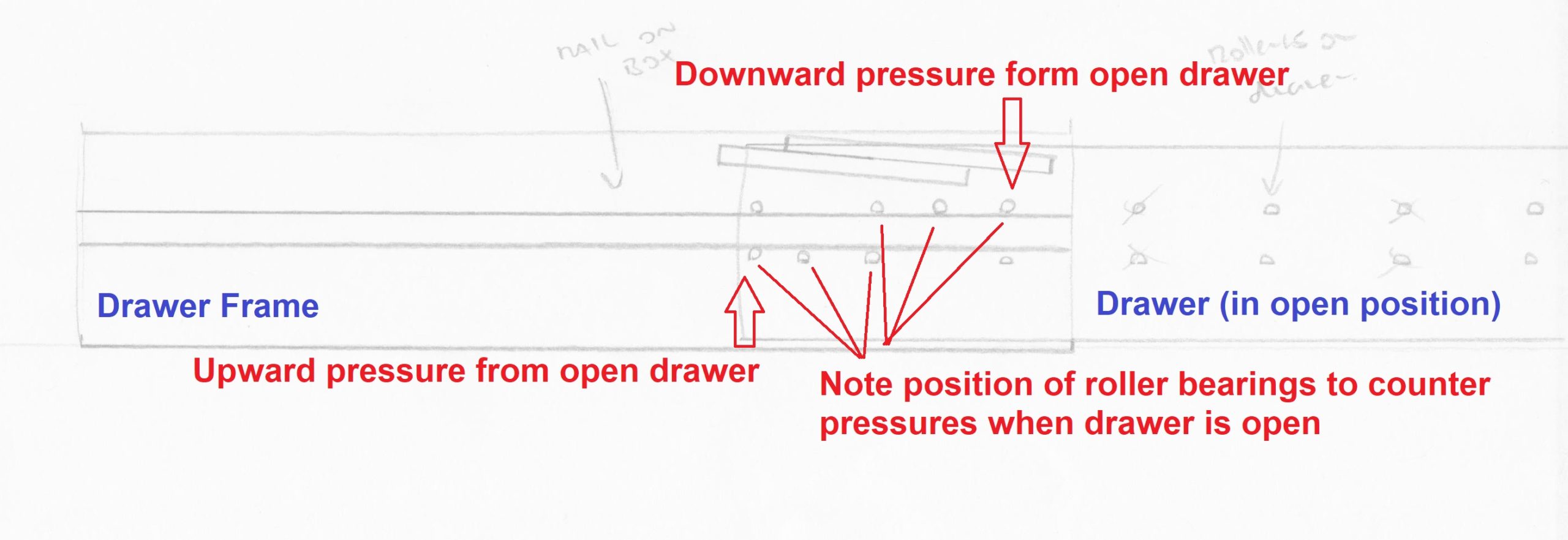
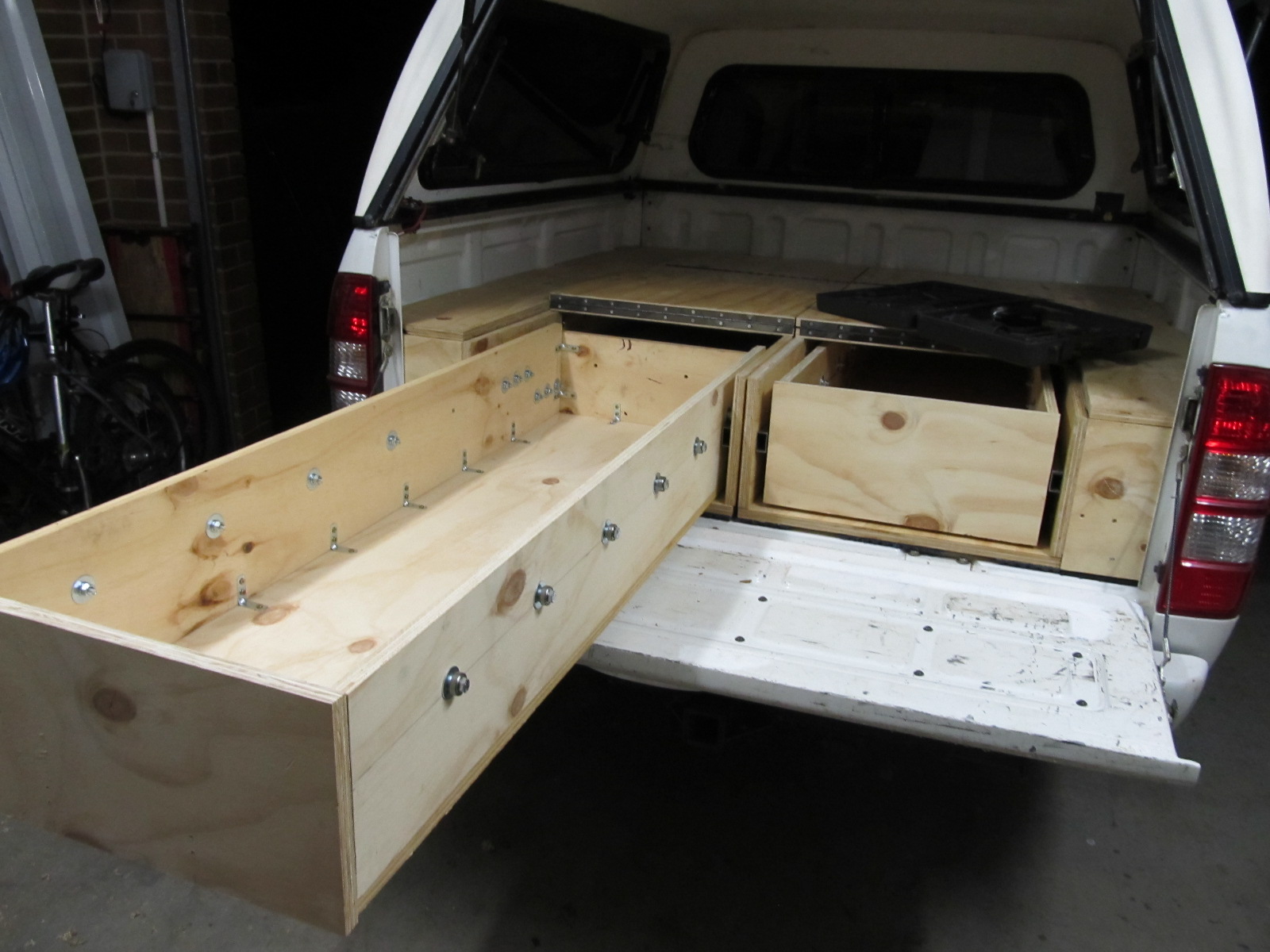
Here are some more pictures of the finished product, to further illustrate the above points.
To stop the drawers from coming out of the drawer frame altogether it is necessary to have a form of stopper. In the case of such large drawers with the potential to carry so much weight it is necessary to have a very solid stopper. I opted for two blocks of ply on each side (outside) of each drawer, which come into contact with two blocks of ply at the opening (inside) of the drawer frame. as depicted in figures 40 & 41. Screwing the block to the drawer frame was easy to do with the drawer out of the frame, however; screwing the block to the outside of the drawer has to be done with the drawer in. to achieve this I jammed the block in place with a magazine and screwed it from the inside of the drawer.
To soften the closing of the drawers, and also to dampen movement and rattling during transit, I glued blocks of medium and high density foam to the inside of the back (front of ute side) of the drawer frame.
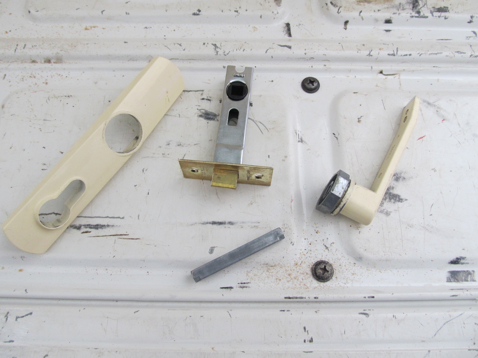
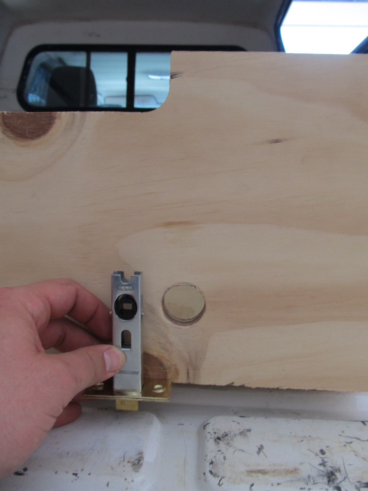
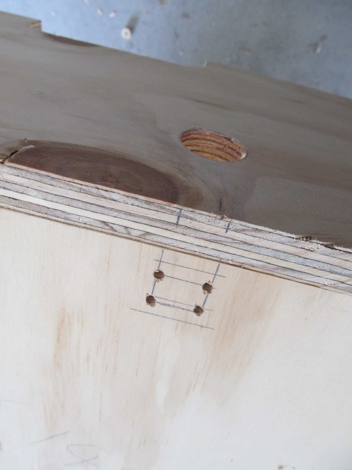
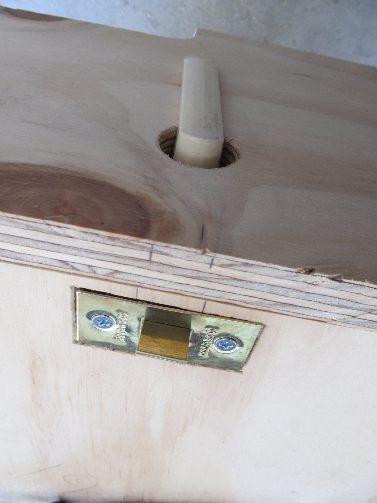
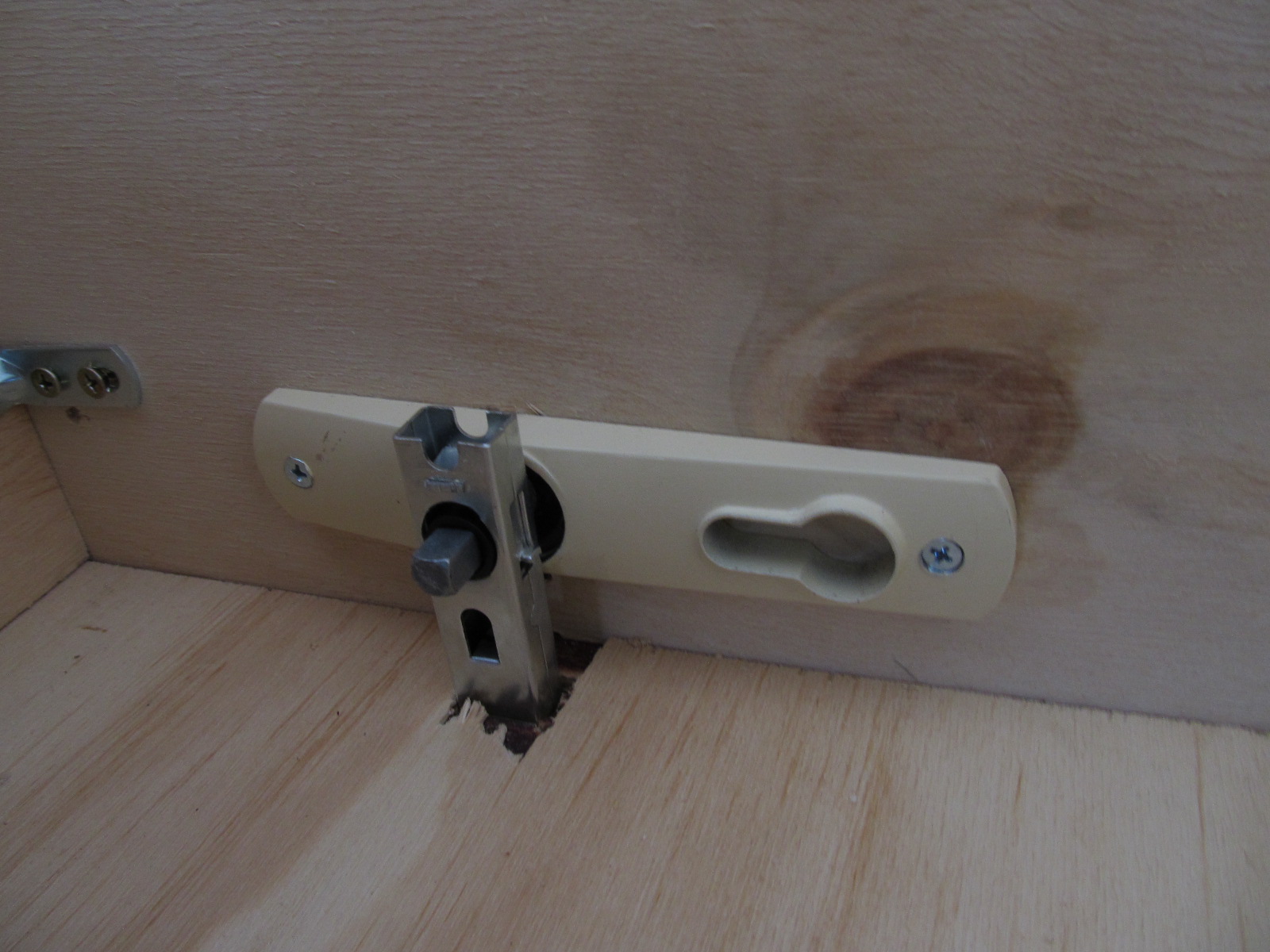
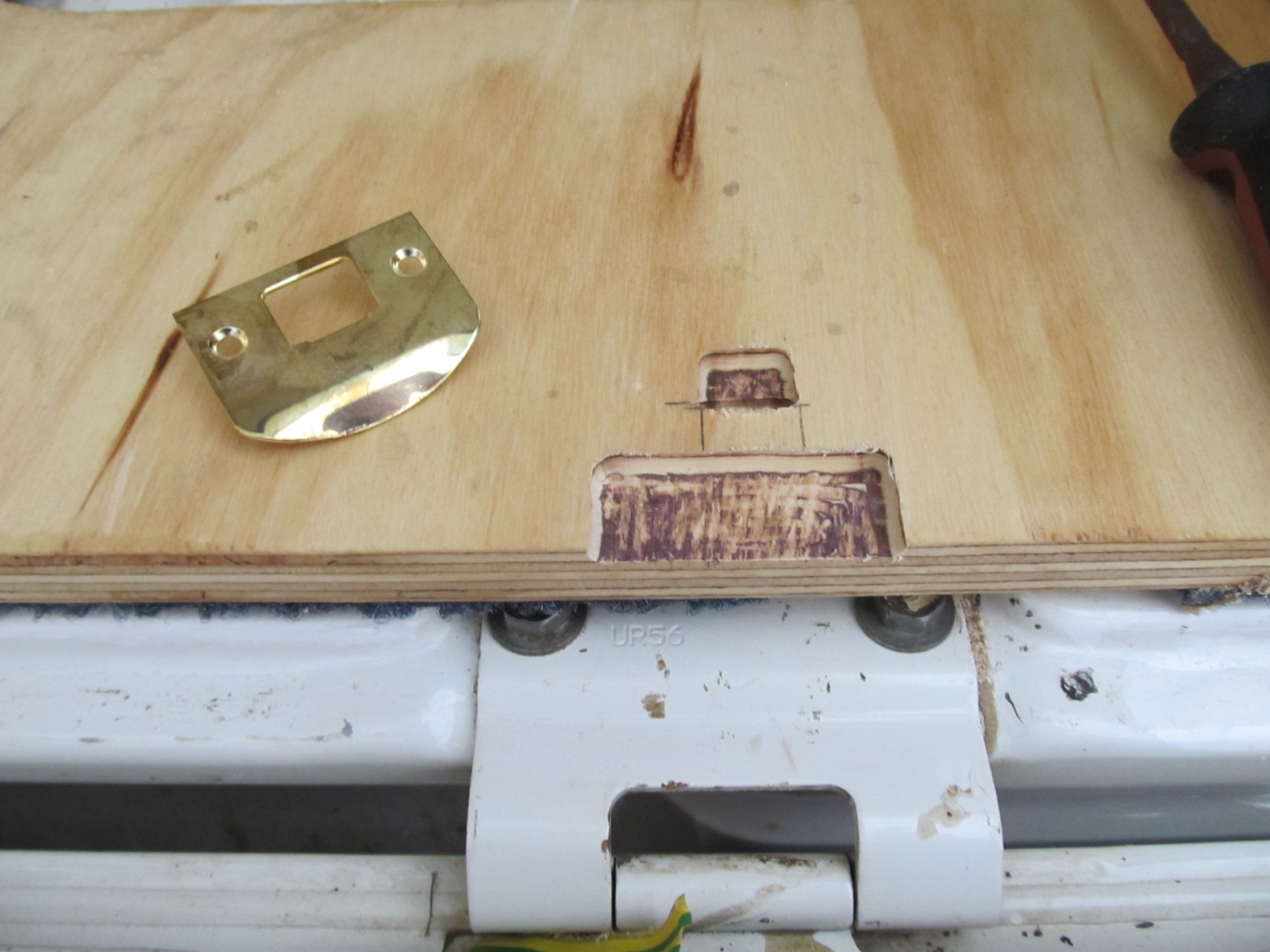
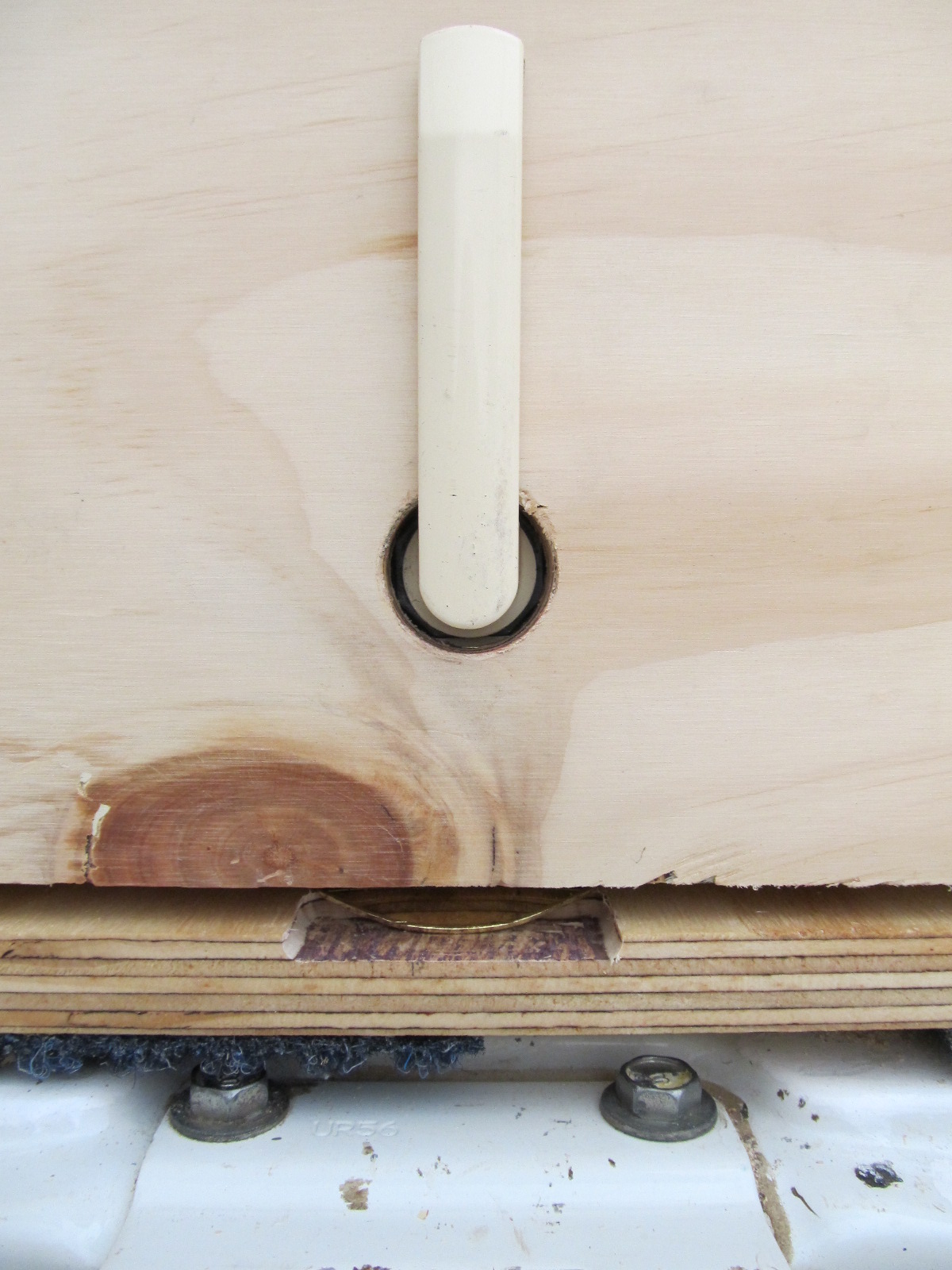
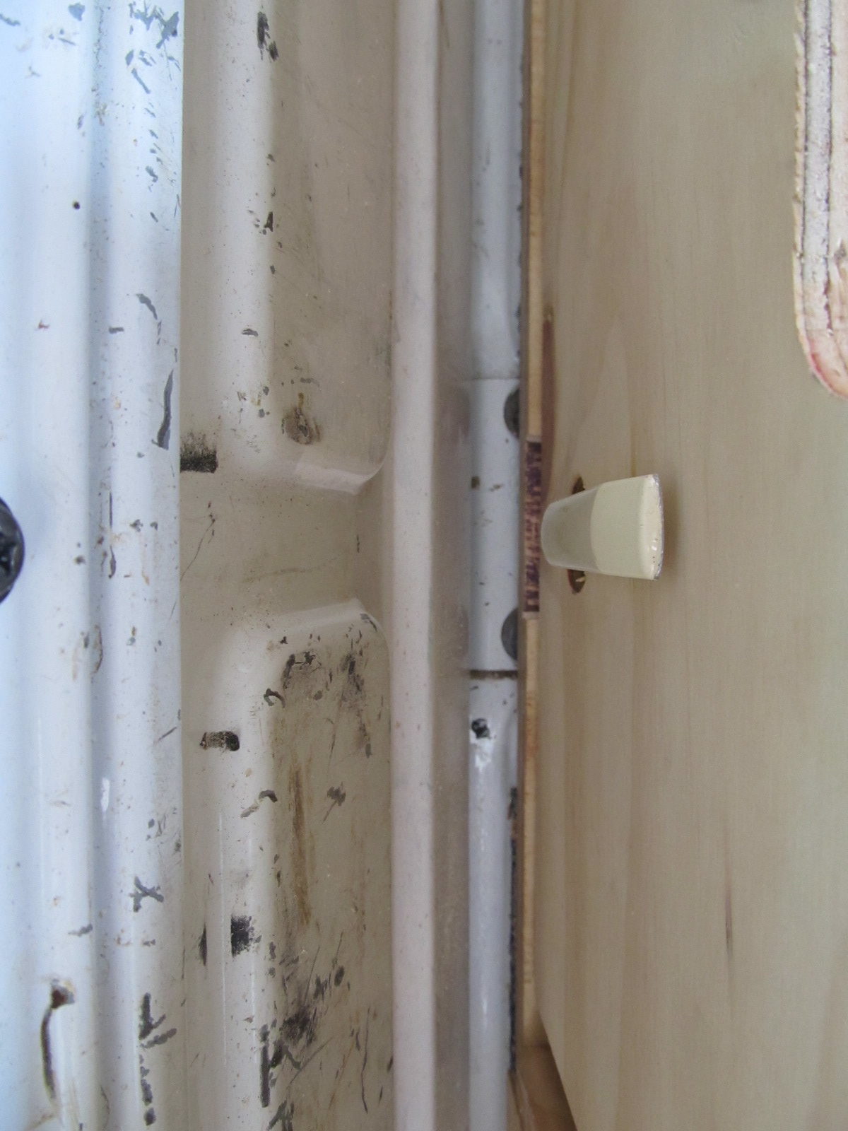
Finally I needed a locking mechanism for the drawers. I noted that most locking mechanism on ute drawers were set onto the front of the drawer and dead-bolted to the drawer frame. Firstly I did not like the fact that this method bushed the front plate of the drawer back, effectively reduced the storage capacity of the drawer by 25-50 mm. And secondly; by this stage I was getting cocky about how well the drawers were going and I decided I was going to do something really chic and classy!….. so off to the dump I went!
This really worked out better than I could have hoped, I’ll let the pictures to the talking.
And that brings me to the end of the job. I hope this helps you with your build and I hope you have as much fun creating as I did.
Regards Wyatt.
FAQs
What would change?
I would put the drawer runners (and roller bearings) lower down, rather than mid-way up the drawer walls. This is because there can be a little bit of flex in the walls and they are more rigid at the bottom where they’re fixed to the base. (not that it’s ever been a problem).
How much did it cost?
Very little! Compared to the an off-the-shelf model or a custom order.
40 x skateboard bearings (ebay) $31.96
100 x Angle brackets (bunnings) $56.50
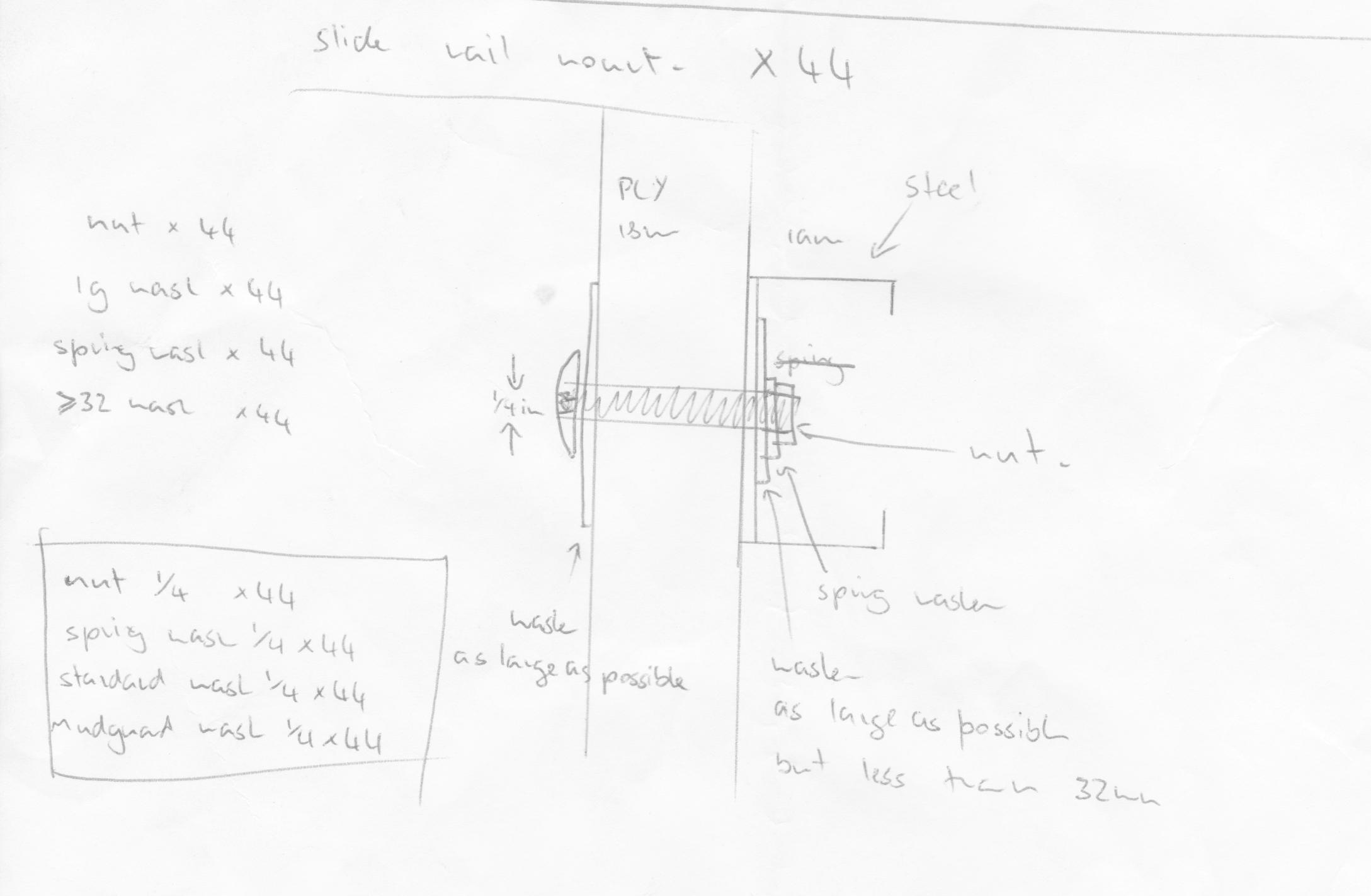
Bolts, washers (specialty fastener shop) $60.07
Hole saw set (ebay) $28.90
Screws 15-18 mm (bunnings) $16.10
3 x sheets Ply 18x1200x2400mm (bunnings) $180.00
Steel 4 metres RHS 38x19x1mm (steel supplier) $38.50
1 x more ply sheet (building re-cyclers) $55.00
Carpet, marine, synthetic (bunnings) $37.00
Varnish 500ml (bunnings) $16.10
carpet adhesive, quik grip 250ml (bunnings) $8.49
Varnish 1000ml (bunnings) $25.20
Paint Brushes (bunnings) $2.00
carpentry square 16x42inch (bunnings) $9.98
2m continuour hinge (bunnings) $12.20
4 x lift off hinges (bunnings) $4.40
Total: $582.40